Disk Array Unit Overview 1-19
DAU Controller
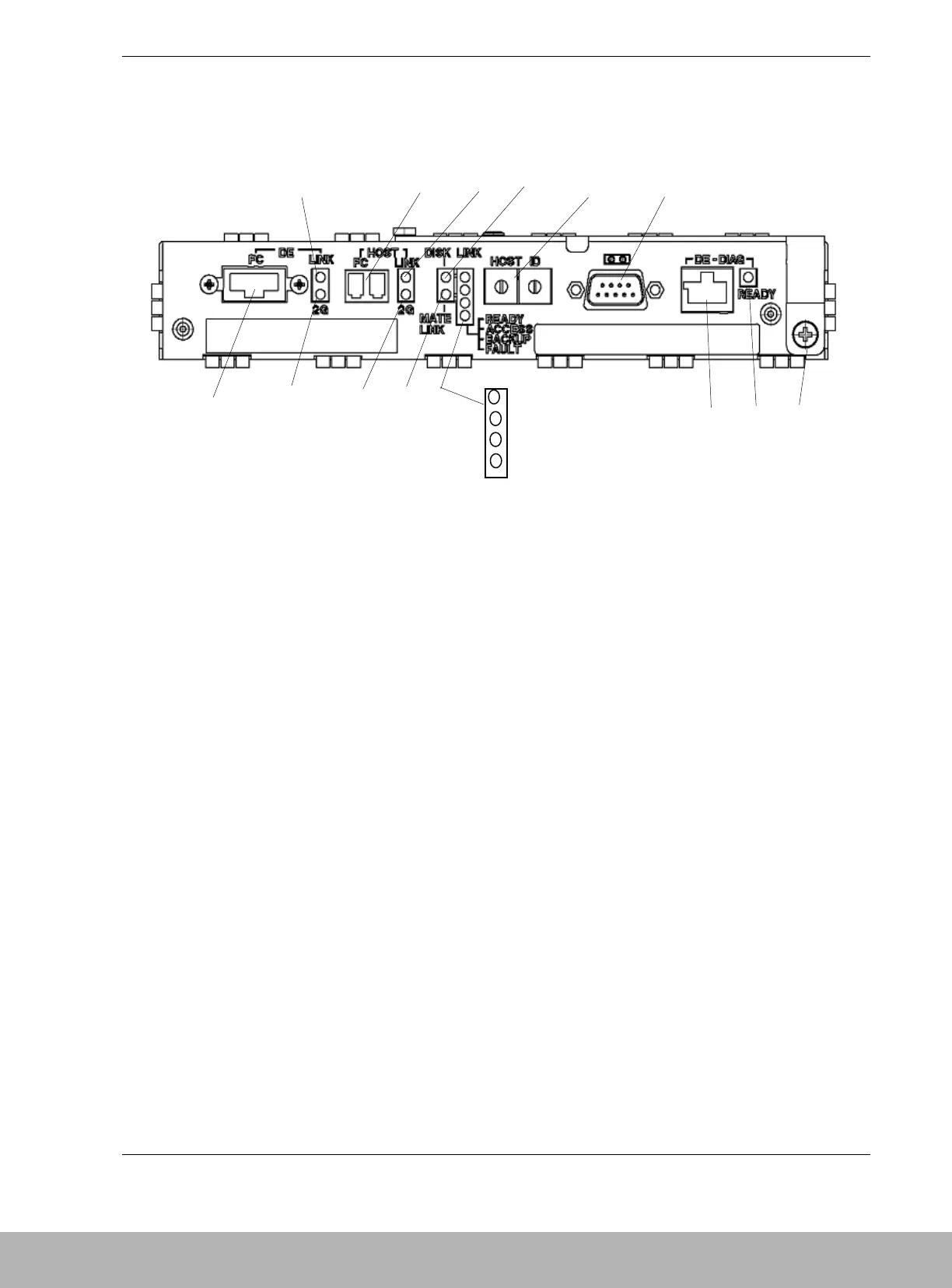
Figure 1-10 shows the features and indicators located on the rear of the DAU controller.
M
A LINKUP LED
(DE-LINK)
This LED lights green if the Disk Enclosure Fibre Channel (DE-FC)
connector (FC port) becomes operable (linked). This LED is off during
self-test or initialization, just after power-on.
B FC Connector Connection between fiber channel controller and the host (HOST-FC).
This connector is used to connect the disk array unit to the basic
processing unit (host).
C LINKUP LED
(HOST LINK)
This LED lights green while the FC interface with the host is operable.
D LINKUP LED
(DISK-LINK)
This LED lights green if the respective disk module becomes operable
(links up). This LED is off during the self-test or initialization, just after
power-on.
E AL-PA switch This switch sets the address of the disk array unit as a fiber channel
device in the fiber channel loop.
At shipment, the addresses of CONT0 and CONT1 are set to "00" and
"01," respectively. Set AL-PA so that the address may not be the same
as that of another fiber channel device in the same host FC loop.
F RS-232C
connector
The RS-232C connector is provided for maintenance of the disk array
unit.
G Ejector This device is used to install and remove the controller.
H DE-DIAG LED
(green)
The DE-DIAG LED lights green when the controller is ready for
diagnosis.
I DE-DIAG
connector
The DE-DIAG connector is provided to connect a cable to the Disk
Enclosure (DE) for diagnosing (monitoring) functions in the DE..
J1 FAULT LED
(orange)
The FAULT LED lights orange if a fault occurs in the controller.