3-12 Adding and Removing Components
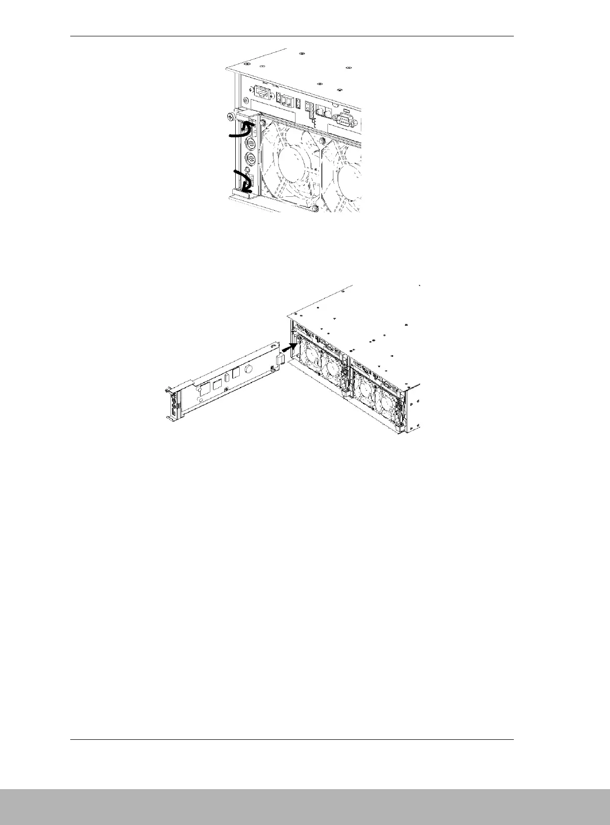
Figure 3-12. Grasping the SVP Service Processor.
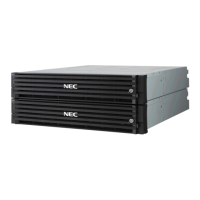
4. Install the replacement SVP Service Processor. See Figure 3-13.
Figure 3-13. Installing the Replacement SVP Service Processor.
5. When the SVP is in position where the finger on the right side of the SVP
service processor is as shown in Figure 3-14, push the projections at the top
and bottom of the SVP Service Processor until it is firmly seated in the
chassis.