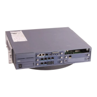
Issue 1.0 VM8000
1 - 4 Quick Setup
SECTION 3 LED INDICATION
1. Power up the system.
N
Remove the grounded wrist strap.
N
Mount the PZ-VM21 onto CD-CP00-US.
N
Install the CD-CP00-US in the SV8100 chassis.
N
Turn the chassis power switch to On.
2. Check the VM8000 InMail LED. See Figure 1-4 Checking LED1.
N
Once the system powers up, check LED1 on the InMail daughter board.
LED1 is viewable on the front panel of the CD-CP00-US.
LED1 will blink quickly only when the InMail CF is being accessed.
SECTION 4 START-UP (DEFAULT) VM8000 INMAIL CONFIGURATION
When you install the VM8000 InMail blade and turn on the system, VM8000 InMail
has the following default programming:
J
Subscriber Mailboxes are enabled for extensions 101-108. The mailbox
numbers are the same as the extension numbers.
J
The Automated Attendant does not answer outside calls.
J
The VM8000 InMail does not answer internal calls.
Figure 1-4 Checking LED1

 Loading...