© by NECTA VENDING SOLUTIONS SpA
10
07-2002 148 03
Installation and the following maintenance operations
should be carried out with the machine switched on and
therefore by qualified personnel only, who are trained in
the correct use of the machine and informed about the
specific risks of such situation.
The machine should be installed in a dry room where
the temperature remains between 2° C and 32° C.
At installation the hydraulic circuits and the parts in
contact with foodstuff should be fully sanitised to
remove any bacteria which might have formed during
storage.
UNPACKING THE VENDING MACHINE
After removing the packing, check that the machine is not
damaged.
If in doubt do not use the machine.
No packing elements (i.e. plastic bags, polystyrene
foam, nails, etc.) should be left within the reach of
children, as they are potentially dangerous.
Packing materials must be disposed of in authorized areas
only, and all recyclable materials must be recovered by
specialised companies.
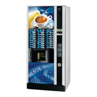
Important notice!!
The machine should be positioned with a maximum inclina-
tion of 2°.
If necessary provide proper levelling by way of the adjust-
able feet included (see Figure 11).
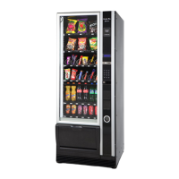
INSERTING THE PRODUCT LABELS
To be able to insert the product labels, the front panel must
be removed. Undo the fastening screws and then press the
clamping tangs (see fig. 12).
The labels must be inserted into the special slots with the
opening positioned alternating on the left and right hand
side.
According to the model, some buttons may not be used
(refer to the selection dose table).
The machine is supplied also with the self-adhesive labels
to be attached to the product containers according to the
layout (refer to the selection dose table).
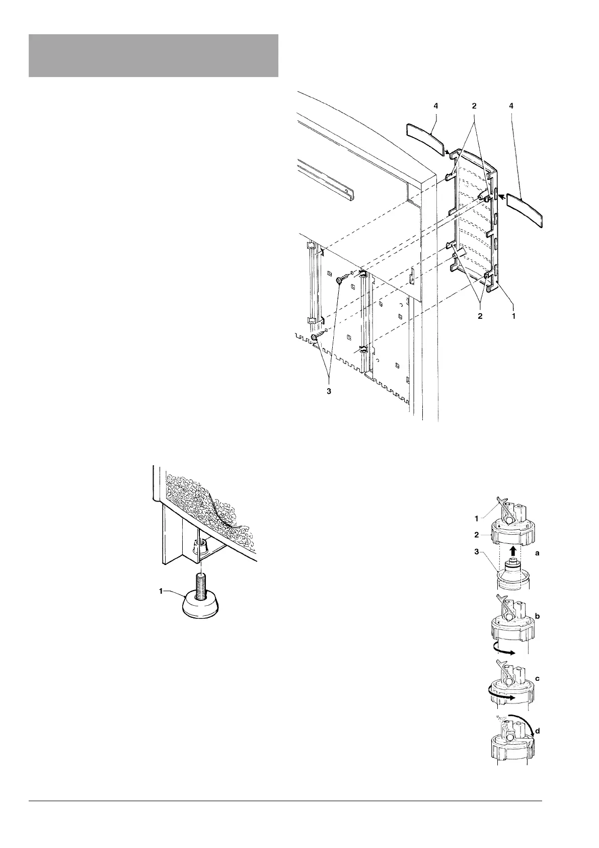
INSTALLING THE
FILTER CARTRIDGE
Make sure that the coloured ring is in the
lower position (turned to the left).
Wet the two cartridge seals (see Fig.
13).
a) insert the cartridge into the ring,
b) turn the cartridge to the right,
c) turn the ring fully to the right until
locking the cartridge;
d) block the ring into place by lowering
the lever, so that it is just in front of the
ring nose.
NOTE: The lever is used as a tap.
lever lifted = tap closed
lever lowered = tap open.
Fig. 12
1 - Label support
2 - Clamping tangs
3 - Fastening screws
4 - Product labels
1 - Lock lever
2 - Coloured ring
3 - Cartridge
Fig. 13
Fig. 11
1 - Adjustable foot
Chapter 2
INSTALLATION
 Loading...