27
© by NECTA VENDING SOLUTIONS SpA 07-2002 148 03
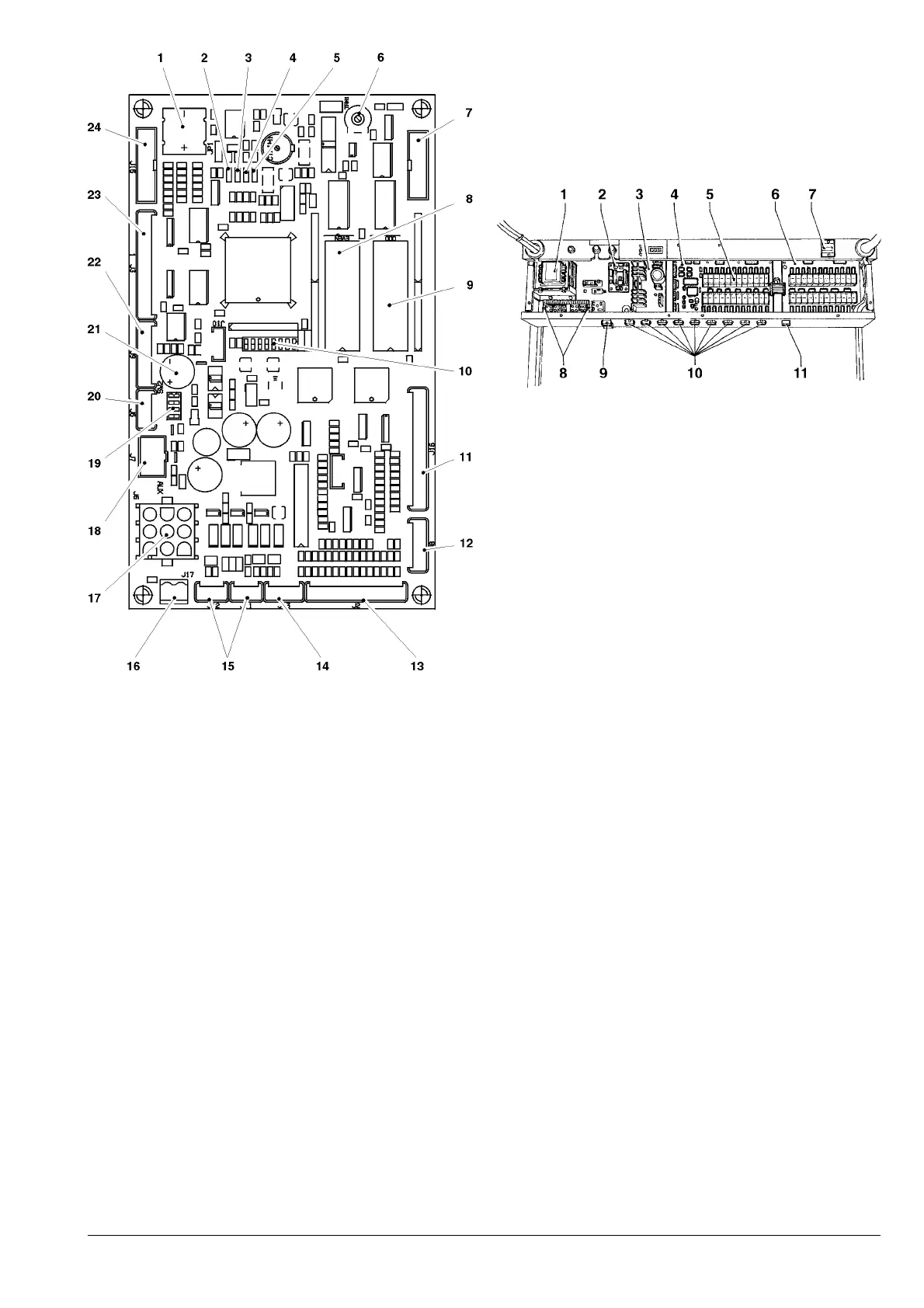
Fig. 20
1 - Battery
2 - Green LED: RUN
3 - Yellow LED: 5 Vdc
4 - Red LED: program error
5 - Red LED: board reset
6 - LCD contrast control trimmer
7 - LCD connector
8 - EPROM: EVEN
9 - EPROM: ODD
10 - Configuration Minidips
11 - Service keys connector
12 - Connector not used
13 - Key-pad connector
14 - Cold unit connector
15 - Connectors for control board communication
16 - 24 Vdc power supply to board
17 - BDV connector
18 - MDB connector
19 - Coin mechanism setting Minidip
20 - Connector not used
21 - Buzzer
22 - RS232 connector to programmer
23 - Connector of cup and sugar control board
BOILER CONTROL BOARD
This board controls the instant boiler heating element.
Fig. 21
1 - Transformer
2 - Boiler control board
3 - Power supply board
4 - Actuation board
5 - Relay
6 - Expansion board
7 - Mechanical counter
8 - Transformer primary/secondary winding fuses
9 - Instant boiler connector
10 - Solenoid valve connector
11 - Sanitising kit connector (optional)
ACTUATION BOARD
This board (see Fig. 22) activates, by means of relays,
some of the 230V~ components of the machine.
This board is powered with 24 VDC.
The control board EPROM is fitted on this board:
- green LED, blinking at intervals of approximately one
second, indicates that the microprocessor is working
correctly; if blinking fast it indicates that there is no
communication with the CPU card.
- red LED “H1”, indicates the operating status of heating
element on the first espresso boiler(if installed).
- red LED “H2”, indicates the operating status of heating
element on the second espresso boiler (if installed).
- red LED “H3”, indicates the operating status of heating
element on the instant boiler.
 Loading...