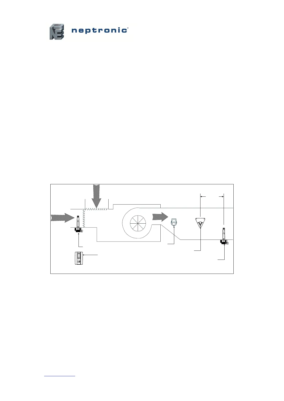
Controls Placement (Steam Dispersed into a Duct or AHU)
A typical humidifier control system includes the following along with the humidifier:
x A wall or return duct humidistat
x A high limit duct humidistat
x An airflow switch
Placement of these devices is critical to the proper operation of the overall system.
x The return air humidistat must always be located in the return air duct, in order to ensure
accurate sensing of the air from the humidified space.
x Alternatively, a room humidistat can be used. The room humidistat must be located on an
inside wall or column. It must not be near any discharge air from supply ducts or sources
of heat or cold.
x The airflow switch must be placed in a position capable of accurately opening on a loss of
air flow, in order to prevent the humidifier from running when there is no air to absorb
humidity.
x The high limit humidistat must be positioned far enough, minimum 4.6 m, downstream of
the steam dispersion manifold(s) to prevent over humidification of the duct that could
result in condensation.
x Any device that may be triggered by high humidity levels in close proximity to the steam
dispersion manifold must also be positioned at 4.6 m, downstream of the dispersion
manifold(s).

 Loading...