EasyManuals Logo

NETGEAR GC510P User Manual

NETGEAR GC510P
36 pages
To Next Page IconTo Next Page
To Previous Page IconTo Previous Page
Page #30 background imageLoading...
Page #30 background image
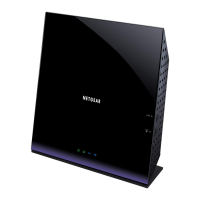
Leave about 6 mm (¼ inch) of each screw protruded from the wall so that you can insert the screws
into the holes on the bottom of the switch.
5. Line up the holes on the bottom panel of the switch with the screws in the wall and mount the switch to
the wall.
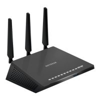
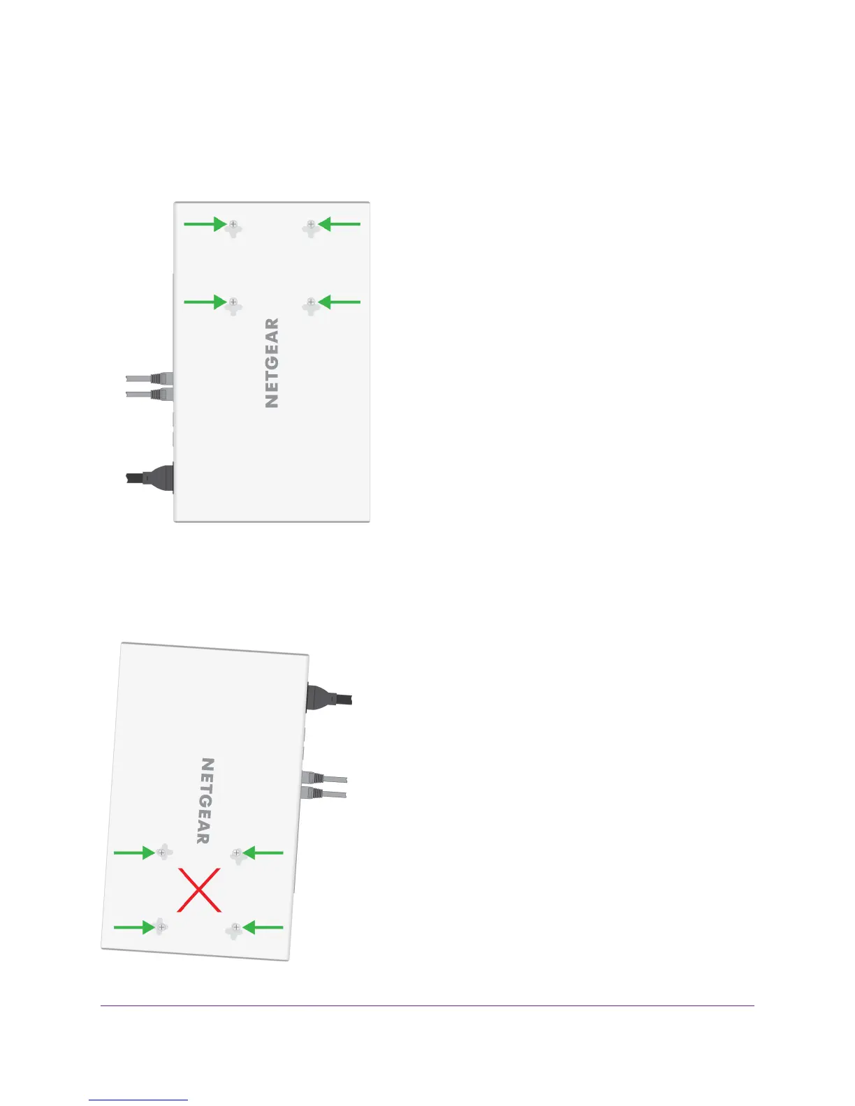
Poor Wall-Mounting Position
To prevent the switch from tilting, do not wall-mount the switch vertically with the back panel facing right
(that is, with the cables on the right). Whether you use two or four screws, the switch will tilt in this position.
Figure 8. Poor wall-mounting position
Installation
30
Insight Managed 8-Port Gigabit Ethernet PoE+ Smart Cloud Switch with 2 SFP Fiber Ports

Questions and Answers:

Question and Answer IconNeed help?

Do you have a question about the NETGEAR GC510P and is the answer not in the manual?

NETGEAR GC510P Specifications

General IconGeneral
Switch typeManaged
Quality of Service (QoS) supportYes
Console portRJ-45
Power connectorDC-in jack
Installed SFP modules quantity2
Installed SFP+ modules quantity0
Basic switching RJ-45 Ethernet ports typeGigabit Ethernet (10/100/1000)
Basic switching RJ-45 Ethernet ports quantity8
10G supportNo
Networking standards-
MAC address table- entries
Product colorGray
AC input voltage100 - 240 V
AC input frequency50 - 60 Hz
Total Power over Ethernet (PoE) budget134 W
Operating temperature (T-T)0 - 45 °C
Weight and Dimensions IconWeight and Dimensions
Depth188 mm
Width314 mm
Height44 mm
Weight2010 g

Related product manuals