Continued Page 10.0R
N
E
M
O
P
U
M
P
E
N
10 DISMANTLING AND ASSEMBLY
OF THE ROTATING PARTS
PAGE
10.0
date name signed revision: 1
issued 19.12.05 Mangel substitute for the issue
approved 20.12.05 Denk dated 25.06.03
released 20.12.05 Denk
text no. 30100
copy to:
10 Dismantling and Assembly of the Rotating Parts
with Pin Joints with SM-Pin Joint Seal
(basic joint size NM015 - NM125)
10.1 Removal of Rotor and Coupling Rod
Where a pump is fitted with a ceramic rotor (1999) the following operations
should be carried out with great care. Do not use any force or sharp tools!
Special care must be taken to prevent heavy strokes, vibrations or impact
by a hammer.
For removal of the rotor (1999) and coupling rod (1998) the pin joints should
be dismantled as follows:
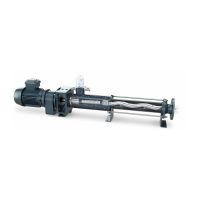
Place the dismantled unit – consisting of drive stool
(0085) with drive (A) and connecting shaft (1050),
coupling rod (1998) and rotor (1999) – on the work-
bench with a wooden block supporting the rotor
(1999).
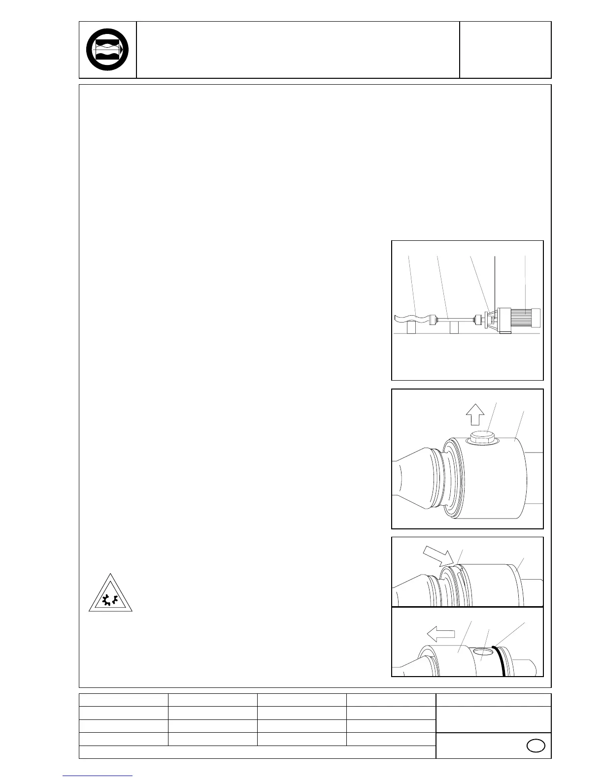
Basic joint size NM125:
Unscrew the wear sleeves (5440) from the head of
rotor (1999) or connecting shaft (1050)
Basic joint size NM021 - NM105:
Push circlip (5065) out of its groove and slip off over
the head of rotor (1999 or connecting shaft (1050).
Pumps fitted with a ceramic rotor (1999):
Carefully turn safety sleeve (5115) with a squeeze
belt wrench, and remove.
The following method should not be employed for
pumps fitted with a ceramic rotor.
Pumps fitted with a metallic rotor (1999):
If necessary hit the edge of sleeve (5115) at an angle
with the help of a wooden block and a plastic ham-
mer. Taking care not to damage the O-rings (8060)!
■
■
■
■
■
GB
1999 10500085 A1998
5065
5440
1050,
1999
1050,
1999
5115 1050,
1999
8060