Continued Page 10.2
10 DISMANTLING AND ASSEMBLY
OF THE ROTATING PARTS
PAGE
10.1R
revision: 1 date name signed
substitute for the issue issued 19.12.05 Mangel
dated 25.06.03 approved 20.12.05 Denk
text no. 30100
released 20.12.05 Denk
copy to:
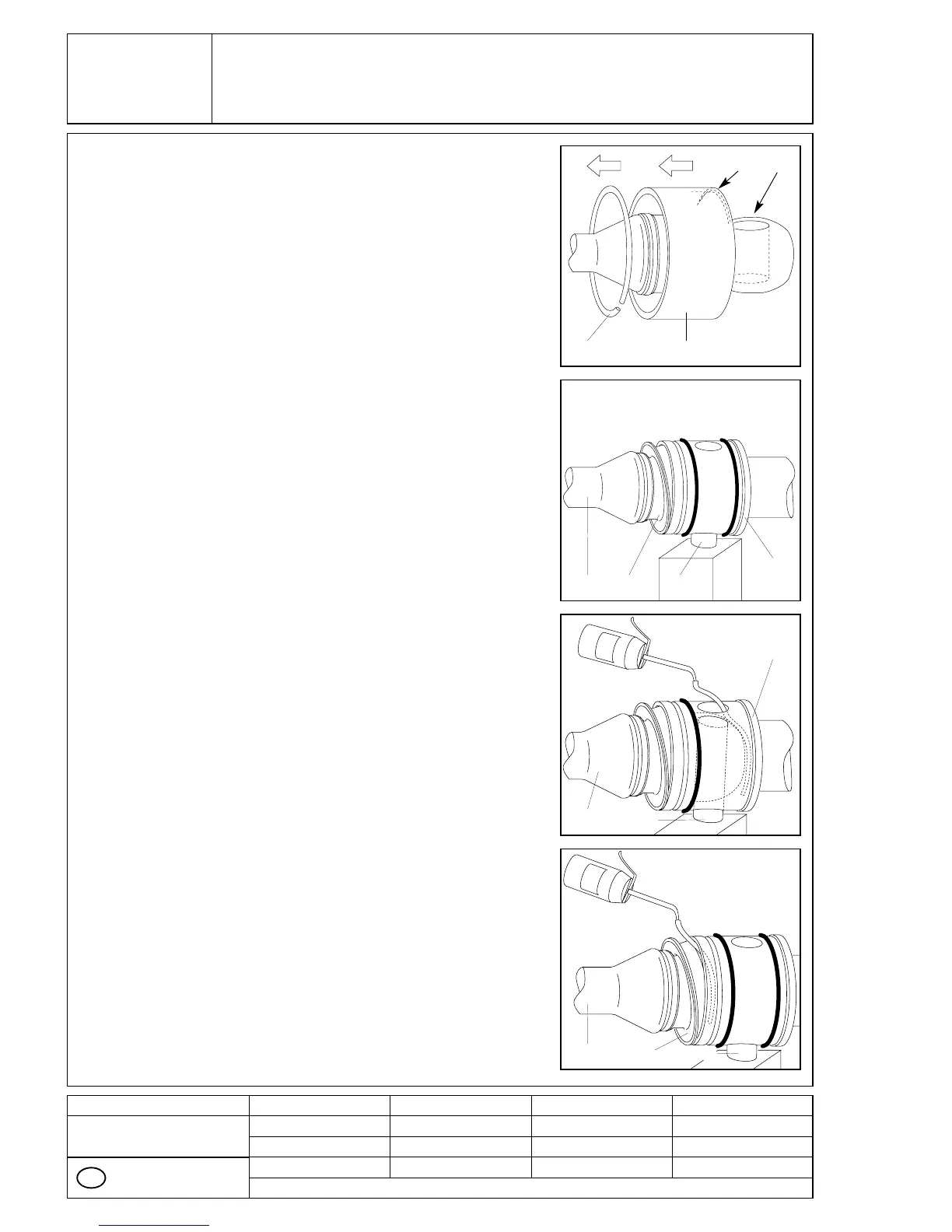
Basic joint size NM021 - NM105:
Slip the circlip (5065) on to the coupling rod (1998).
Slide the sleeve (5115) on to coupling rod (1998) so
the inside diameter of chamfering (A) is being pla-
ced towards the coupling rod (1998) extension.
Chamfering (A) will later on ease the installation
over the O-rings (8060).
Orient the head of coupling rod (1998) until it is in
vertical position for the bore (B) for the pin (5075).
Slide the coupling rod (1998) with SM-pin joint seal
(8235) into the bore of rotor (1999) or connecting
shaft (1050) and insert the pin (5075) from below and
push up to the upper edge of coupling rod (1998).
Support the pin (5075) against dropping out.
Slide the SM-pin joint seal (8235) into the rotor
(1999) or connecting shaft (1050) only from below,
and in a slightly slanted position.
For lubrication, use an oil can which should be
fitted with a thin plastic hose having an outside dia-
meter of not more than 4 mm.
Insert this hose into the upper oil port opening in
the rotor (1999) or connecting shaft (1050). Then
slide the hose end past the coupling rod (1998)
all the way down to the bottom section of the rotor
head (1999) or connecting shaft (1050).
Slowly fill with lubricating oil up to the filling port.
Pull the hose out.
Then insert the hose end through the small gap on
the topside of SM-pin joint seal (8235) and guide it
down to the bottom of the hollow space between
coupling rod (1998) and SM-pin joint seal (8235).
Slowly fill with lubricating oil up to the gap.
■
■
■
■
5065
1998
1998
1998
8235 5075
5075
8235 5075
1050
1999
1050
1999
5115
A B
GB