Continued Page 10.3
10 DISMANTLING AND ASSEMBLY
OF THE ROTATING PARTS
PAGE
10.2R
revision: date name signed
substitute for the issue issued 19.12.05 Mangel
dated approved 20.12.05 Denk
text no. 30100
released 20.12.05 Denk
copy to:
GB
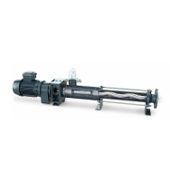
For lubrication, use an oil can which should be
fitted with a thin plastic hose having an outside dia-
meter of not more than 4 mm.
Insert this hose into the upper oil port opening in
the rotor (1999) or connecting shaft (1050). Then
slide the hose end past the coupling rod (1998)
all the way down to the bottom section of the rotor
head (1999) or connecting shaft (1050).
Slowly fill with lubricating oil up to the filling port.
Pull the hose out.
Then insert the hose end through the small gap on
the topside of SM-pin joint seal (8235) and guide it
down to the bottom of the hollow space between
coupling rod (1998) and SM-pin joint seal (8235).
Slowly fill with lubricating oil up to the gap.
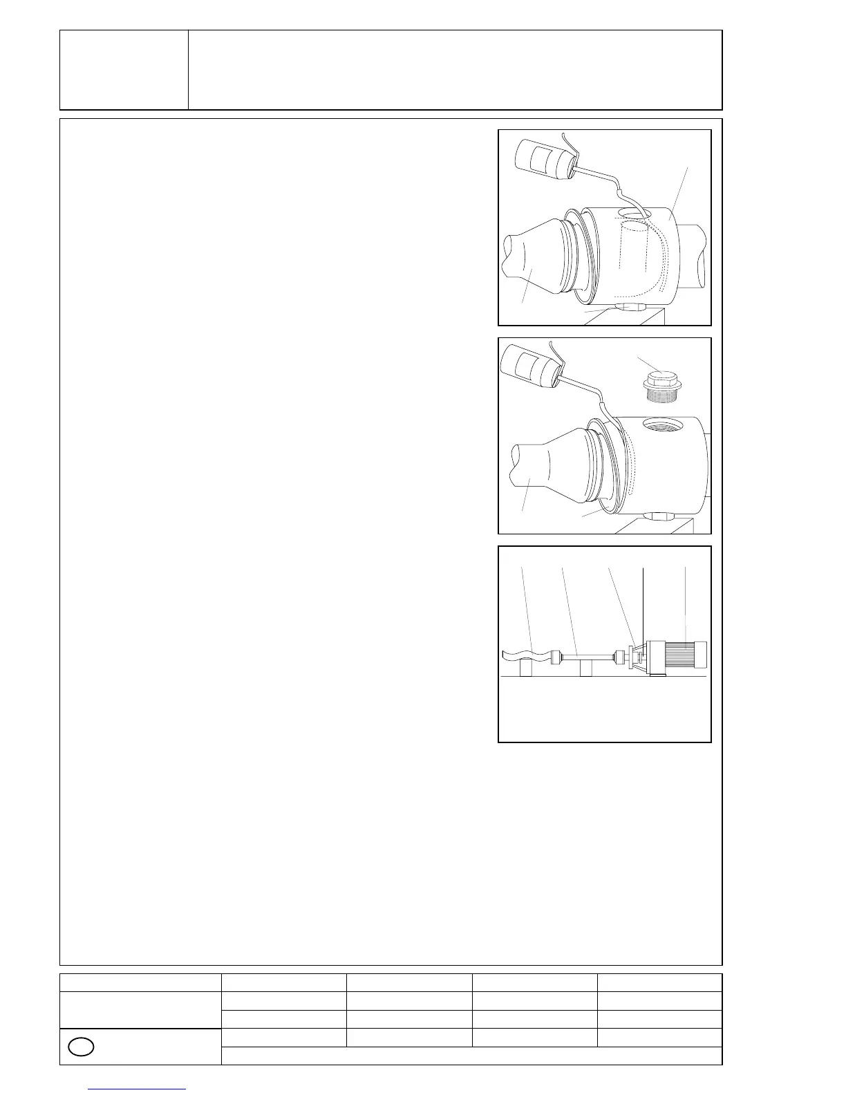
Screw in the second wear sleeve (5440) with O-ring
(8060) into the head of rotor (1999) and connecting
shaft (1050).
■
■
■
1998
1998
5440
8235
5440
1050
1999
Basic joint size NM021 - NM125:
Drive connecting shaft (1050), coupling rod (1998)
and rotor (1999) are now joined by means of the two
pin joints.
Pump housing (2010), stator (3005) and end stud
(2005) may now be fitted.
■
1999 10500085 A1998