4
PART 2 HARDWARE
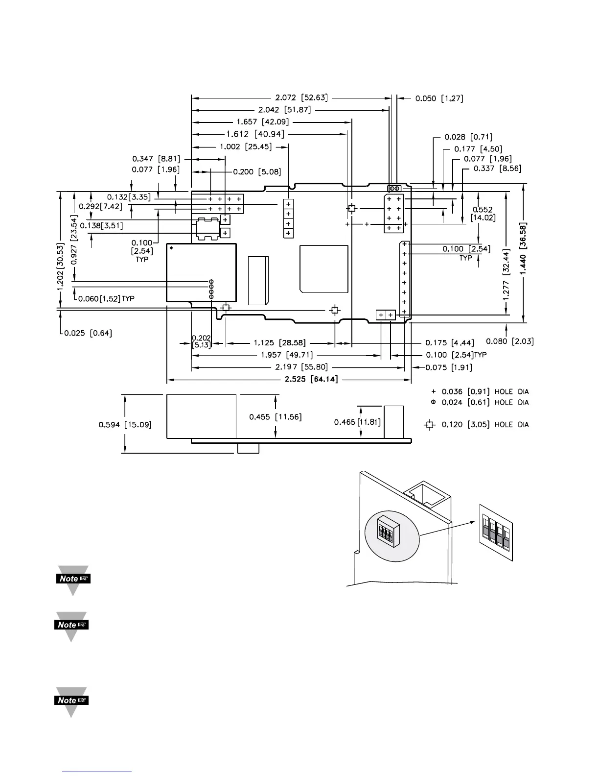
2.1 Mounting
Position unit where required. Mark and drill holes as required.
Figure 2.1 Mounting
2.2 DIP Switches
1 To change the IP address, gateway address,
and subnet mask from the serial port
2 To change to default factory settings
3 To enable/disable DHCP
4 To enable/disable Terminal Server function
The iServer is shipped with all
DIP switches in "OFF" position
To set the iServer to factory default settings, slide DIP switch #2 to ON position. Power the
iServer on and wait about 10 seconds until the iServer fully boots up. Set the DIP switch
#2 back to OFF position (it does not matter if the iServer is powered ON or OFF, just make
sure that the DIP switch is set to OFF, otherwise, every time the unit is power-cycled the
factory settings will take over. See Section 4.6 for setting the iServer to factory default
using the firmware (over the LAN).
To enable the DHCP, besides using DIP switch #3, set the iServer’s IP address to 0.0.0.0.
An iServer with IP address of 0.0.0.0 will request an IP address, gateway address, and
subnet mask from the DHCP server over the Ethernet.