6
2.4 Serial Communication Interfaces
Two communication interfaces are supported in the standard iServer: RS232 and
RS485. In addition, the serial port can also be provided with TTL logic on request.
These standards define the electrical characteristics of a communication network. The
RS485 port of the iServer is fully compatible to use with RS485 and RS422 instruments.
The RS485 is an extended version of the RS422 communication standard which
increases the allowable number of devices from 10 to 32 by improving the electrical
characteristics.
• The RS232 standard (point-to-point) allows a single device to be connected to an
iServer. The iServer operates with full-duplex RS232 using eight wires: Rx-receive,
Tx-transmit, DTR, DSR, DCD, CTS, RTS and common ground wires. RS232 cable
length is limited to 50 feet.
• The RS485 standard (multi-point) allows one or more devices (multi-dropped) to be
connected to the iServer using a two-wire connection (half-duplex) +Rx/+Tx and
–Rx/-Tx. Use of RS485 communications allows up to 31 devices to connect to the
iServer with cable length up to 4000 feet long.
Although the RS485 is commonly referred to as a "two wire" connection, the
iServer also provides a ground/return shield connection to use as a common
connection for EMI noise protection.
• The TTL standard (point-to-point) allows a single device to be connected to an
iServer. The iServer operates with full-duplex TTL using three wires:Rx-receive,
Tx-transmit, and common ground wires.
Table 2.2 shows the differences between RS232 and RS485 communication interfaces.
Table 2.2
Data Transmission Characteristics RS232 RS485
Transmission Mode Single ended Differential
Electrical connections 8 wire 2 wire
Drivers per line 1 driver 32 drivers
Receivers per line 1 receiver 32 receiver
Maximum cable length 50 ft (15 meters) 4000 ft (1200 meters)
Changing between RS232 and RS485 interfaces, as well as modifying the
other parameters is possible through the iServer firmware using its home Web
page or Telnet connection (see Part 4 for details).
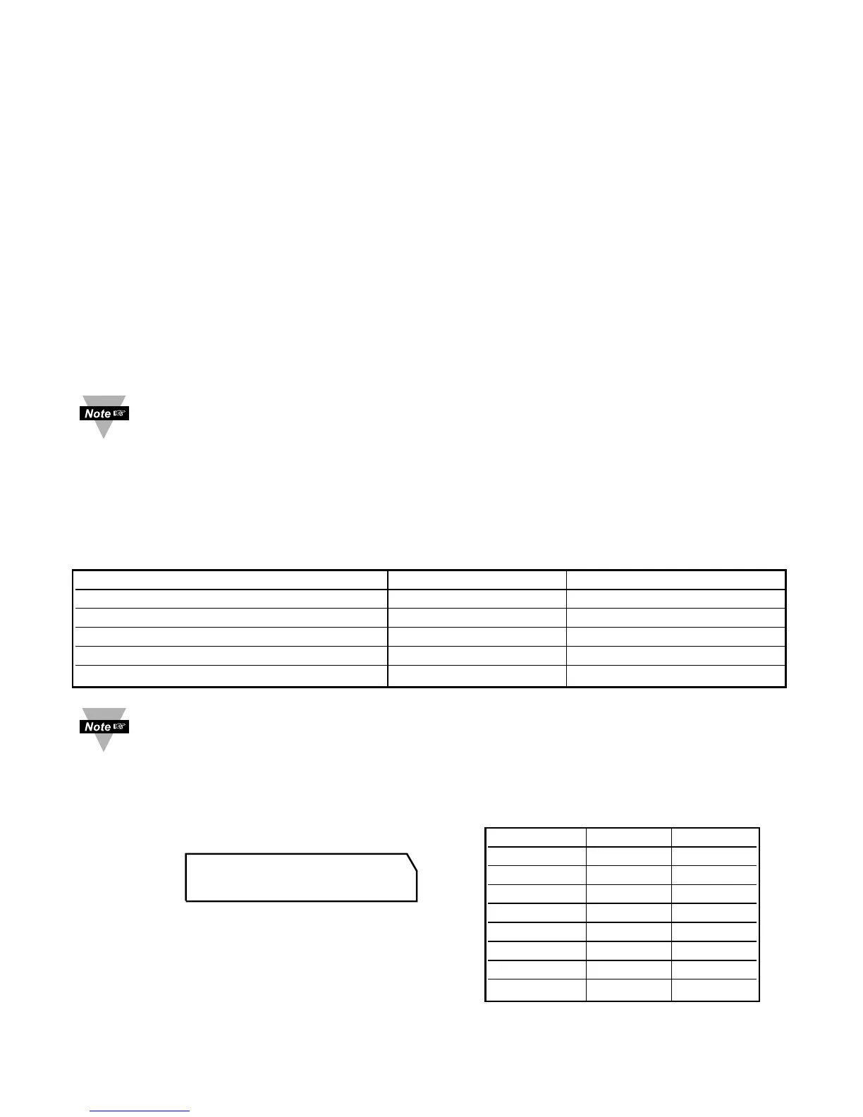
2.4.1 Wiring RS232 Interface
Table 2.3 shows the signals and the direction of
signals on the DB9 (DTE configuration) RS-232
Serial Port.
J16A Pin # Signal Direction
1 +5V --
2 GND --
3 Tx OUT
4RxIN
* 5 CTS IN
* 6 RTS OUT
* 7 DCD IN
* 8 DTR OUT
* These 4 pins can also be used as digital
input/output signals (firmware selection)
+5V
GND
Tx (OUT)
Rx (IN)
CTS (IN)
RTS (OUT)
DCD (IN)
DTR (OUT)
8 7 6 5 4 3 2 1
J16A
Figure 2.4 J16A Connector
Table 2.3