7
2.4.2 Wiring TTL Interface
Table 2.4 shows the connector locations for Tx and Rx
signals for the TTL interface. The ground and +5Vdc can be
connected according to Table 2.3.
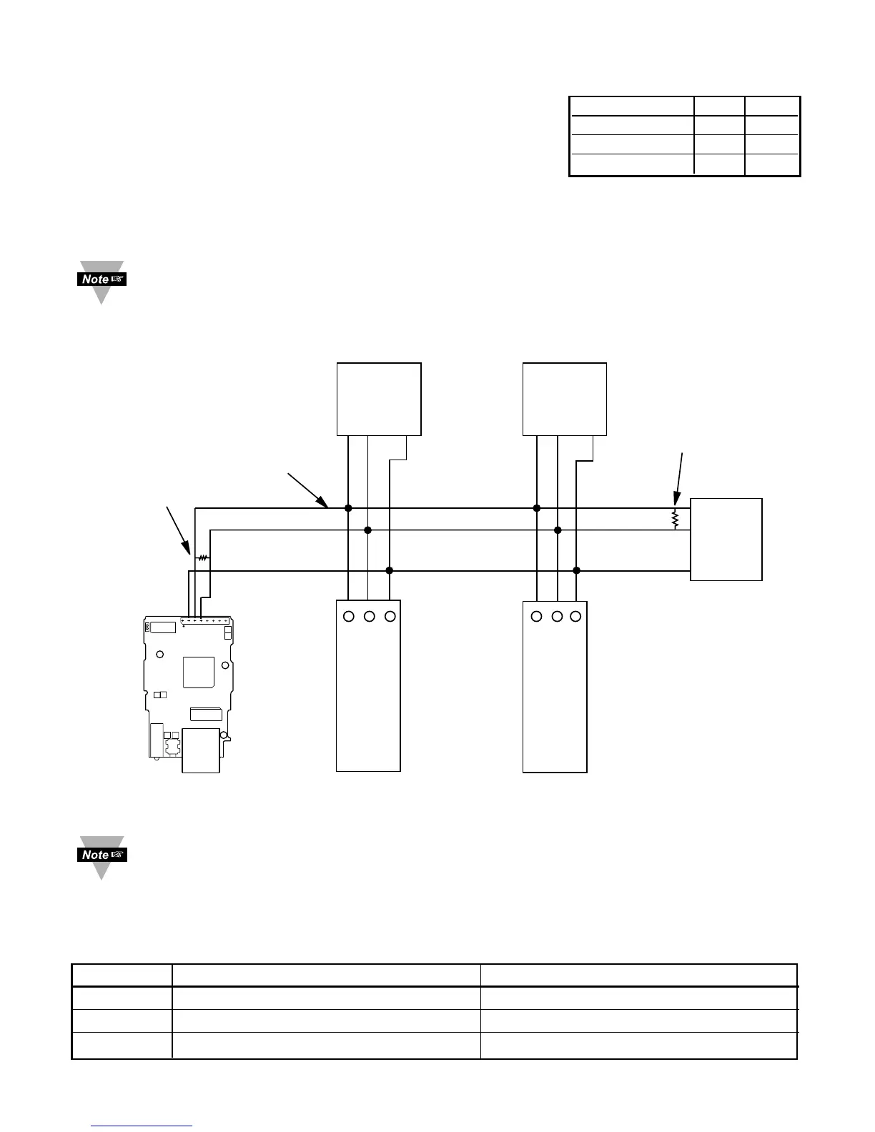
2.4.3 Wiring RS485 Interface
RS485 interface uses a two-wire communication system (one for transmitting and one for
receiving) plus a common wire to connect to the shield of the cable. It is recommended
to use a shielded cable with one twisted pair.
Use of twisted pair and shield will significantly improve noise immunity.
Figure 2.5 shows multi-point, half-duplex RS485 interface connections for the iServer.
Figure 2.5 Multi-point, Half-Duplex RS485 Wiring
Value of the termination resistor is not critical and depends on the cable
impedance.
Table 2.5 shows RS485 half-duplex hookup between the iServer serial port and device
with RS485 communication interface.
Table 2.5
Pin# iServer DEVICE WITH RS485
2
RTN (Common GND) GND (Common GND)
3 -Tx/-Rx (-Transmit/-Receive) -Tx/-Rx (-Transmit/-Receive)
4
+Tx/+Rx (+Transmit/+Receive) +Tx/+Rx (+Transmit/+Receive)
DEVICE #1
DEVICE #29
DEVICE #31
DEVICE #30
DEVICE #2EIS-PCB iServer
120 Ohm
Termination
resistor
GND
-Tx/-Rx
+Tx/+Rx
+Tx/+Rx
-Tx/-Rx
Twisted
shielded
pair
-Tx/-Rx
-Tx/-Rx-Tx/-Rx
-Tx/-Rx
+Tx/+Rx
+Tx/+Rx
GND
GND
GND
GND
+Tx/+Rx
+Tx/+Rx
.........................
.........................
...............................
...............................
120 Ohm
Termination
resistor
4
3
2
ETHERNET
J16A
2
3
4