EasyManua.ls Logo

Newport iServer MicroServer EIS-PCB - Parts of Iserver Unit; Figure 2.3 Parts of the Iserver Unit; Table 2.1 Parts of Iserver Unit

Default Icon
56 pages
Print Icon
To Next Page IconTo Next Page
To Previous Page IconTo Previous Page
Loading...
5
2.3 Parts of the iServer Unit
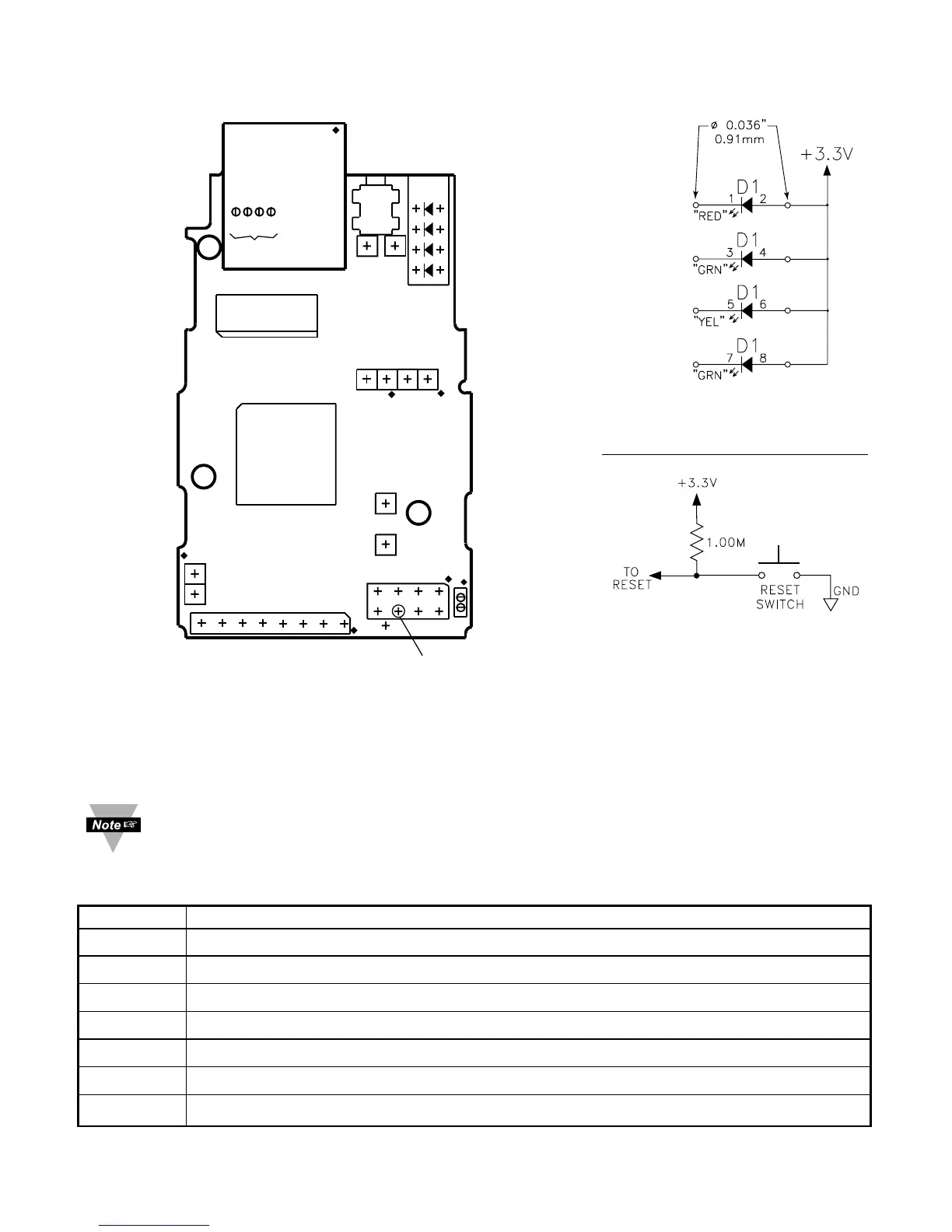
Figure 2.3 Parts of the iServer Unit
Pin headers can be installed on either side of the board for the serial interface
(J16A), in place of RJ45 Ethernet port (J17), Reset Switch (J18), and in place of
the LEDs.
Table 2.1 Parts of iServer Unit
SERIAL J16A for RS-232 / RS-485 / RS-422 connections / (firmware selectable).
ETHERNET RJ45 interface for 10BASE-T connection.
RESET Button: Used for power reseting the iServer.
ACTIVITY LED (Red) Blinking: Indicates network activities (receiving or sending packets).
NET LINK LED (Green) Solid: Indicates good network link.
TX LED (Yellow) Blinking: Indicates transmitting data to the serial port.
RX LED (Green) Blinking: Indicates receiving data on the serial port.
JTAG J1 is the JTAG Connector used for upgrading firmware revision.
J12
ETHERNET
RJ45
ACTIVITY (RED)
NETWORK LINK (GREEN)
TX TRANSMIT (YELLOW)
RX RECEIVE (GREEN)
RESET
SWITCH
J8
+5V
J9
GND
J6
+5V
GND
LED
J15
RX (IN)
TX (OUT)
J18
RST PWR
GND
RX (IN)
TX (OUT)
J16A
+5V
GND
TX (OUT)
RX (IN)
CTS (IN)
RTS (OUT)
DCD (IN)
DTR (OUT)
GND
+5V
J1
JTAG
MNTG
HOLE
MOUNTING
HOLE
MOUNTING
HOLE
4 3 2 1
ANODE
CATHODE
+3.3V
1
2
1
2
1
2
3
4
5
6
7
8
1
3
5
7
1
2
1
2
J10
P11
J17
Reference schematic
for wiring remote LED.
Reference schematic for
wiring remote Reset Switch

Table of Contents