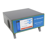
XPS-Q8 Controller User’s Manual
I/O • 30 TTL inputs and 30 TTL outputs (open-collector)
• 4 synch. analog inputs ±10 V, 14 Bit
• 4 synch. uncommitted analog outputs, 16 Bit
• Watchdog timer and remote interlock
Trigger In • Hardware latch of all positions and all analog I/O’s; 8 kHz max. frequency
• <50 ns latency on positions
• <100 µs time jitter on analog I/O’s
Trigger Out • One high-speed position compare output per axes that can be either configured for position
synchronized pulses or for time synchronized pulses : <50 ns accuracy/latency, 2.5 MHz max.
Dedicated Inputs Per Axis • RS-422 differential inputs for A, B and I, Max. 25 MHz, over-velocity and quadrature error
detection
• 1 Vpp analog encoder input up to x32768 interpolation used for servo; amplitude, phase and
offset correction; additional 2nd hardware interpolator used for synchronization; up to x200
interpolation
• Forward and reverse limit, home, error input
Dedicated Outputs Per Axis
(when using external drives)
2 channel 16-bit, ±10 V D/A
Drive enable, error output
• Analog voltage, analog velocity, and analog acceleration (used with XPS-DRV01 and
XPS-DRV03 for DC brush motor control).
• Analog position (used with XPS-DRV01 for stepper motor control or with the XPS-DRVP1
for piezo control)
• Analog position (used with external drives for example 3rd party motors)
• Analog acceleration, sine acceleration and dual sine acceleration (used with XPS-DRV02 for
brushless motors control)
• Step and direction and +/- pulse mode for stepper motors (requires XPS-DRV00P and external
stepper motor driver)
• 500 W @ 230 VAC and 425 W @ 115 VAC total available power
AC Power Requirements • 100–240 VAC 60/50 Hz 10 A–5.5 A The controller should be connected to a power
installation that incorporates appropriate protection devices. Refer to the installation
requirements of your facility and local applicable Standards concerning the use of RCDs
(residual current device).
2.2 Drive Options
The XPS controller is capable of driving up to 8 axes of most Newport positioners using
driver cards that slide through the back of the chassis. These factory-tested drives are
powered by an internal 500 W power supply, which is independent of the controller
power supply. When used with Newport ESP stages, the configuration of the driver
cards is easy using the auto-configuration utility software. Advanced users can also
manually develop their own configuration files optimized for specific applications.
The XPS-DRV01 is a software configurable PWM amplifier that is compatible with
most of Newport’s and other companies’ DC brush and stepper motor positioners.
The XPS-DRV01 motor driver supplies a maximum current of 3 Amps and 48 Volts. It
has the capability to drive bipolar stepper motors in microstep mode (sine/cosine
commutation) and DC brush motors in velocity mode, for motors with tachometer, or
voltage mode, for motors without tachometer. Programmable gains and a programmable
PWM switching frequency up to 300 kHz allow a very fine adjustment of the driver to
the motor. For added safety, a programmable over-current protection setting is also
available.
7 XPSDocumentation V1.4.x (EDH0301En1060 — 10/17)
 Loading...

