XPS-Q8 Controller Appendix
24.0 Appendix F: Motor Driver Cards
24.1 DC and Stepper Motor Driver XPS-DRV01
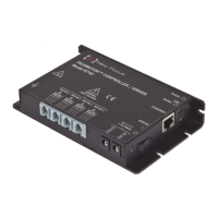
Figure 71:XPS-DRV01 Motor Driver Connectors.
Motor + This output must be connected to the positive lead of the DC
motor. The voltage seen at this pin is pulse-width modulated with
maximum amplitude of 48 V DC.
Motor - This output must be connected to the negative lead of the DC
motor. The voltage seen at this pin is pulse-width modulated with
maximum amplitude of 48 V DC.
Ph1 This output must be connected to Winding A+ lead of a two-phase
stepper motor. The voltage seen at this pin is pulse-width
modulated with maximum amplitude of 48 V DC.
Ph2 This output must be connected to Winding A- lead of a two-phase
stepper motor. The voltage seen at this pin is pulse-width
modulated with maximum amplitude of 48 V DC.
Ph3 This output must be connected to Winding B+ lead of a two-phase
stepper motor. The voltage seen at this pin is pulse-width
modulated with maximum amplitude of 48 V DC.
Ph4 This output must be connected to Winding B- lead of a two-phase
stepper motor. The voltage seen at this pin is pulse-width
modulated with maximum amplitude of 48 V DC.
Common 3&4 This output must be connected to the center tab of Winding B of a
two-phase stepper motor. The voltage seen at this pin is pulse-
width modulated with maximum amplitude of 48 V DC.
Common 1&2 This output must be connected to the center tab of Winding A of a
two-phase stepper motor. The voltage seen at this pin is pulse-
width modulated with maximum amplitude of 48 V DC.
+ Travel limit This input is pulled-up to +5 V with a 2.2 kΩ resistor by the
controller and represents the stage positive direction hardware
travel limit.
- Travel limit This input is pulled-up to +5 V with a 2.2 kΩ resistor by the
controller and represents the stage negative direction hardware
travel limit.
Encoder A & /A These A and /A inputs are differential inputs. Signals are
compliant with RS422 electrical standard and are received with a
213 XPSDocumentation V1.4.x (EDH0301En1060 — 10/17)
 Loading...

