Do you have a question about the Nexcom NEX 605 and is the answer not in the manual?
Includes copyright, disclaimer, and acknowledgements information for the manual and product.
Details FCC and CE compliance statements and requirements for the system.
Outlines NEXCOM's environmental policy regarding RoHS compliance and product recognition.
Specifies the warranty duration and conditions for NEXCOM products.
Details the procedure for returning products for repair or replacement under warranty.
Provides essential warnings, cautions, and safety information for device installation and operation.
Offers guidance on setting up a suitable environment and using proper tools for installation.
Lists critical safety instructions for operating and maintaining the equipment.
Provides information on obtaining technical support and necessary details for inquiries.
Explains symbols and conventions used throughout the user manual for clarity.
Contact details for the NEXCOM headquarters in Taiwan.
Contact information for NEXCOM France.
Contact information for NEXCOM EUROPE in the UK.
Contact information for NEXCOM USA.
Contact information for NEXCOM GmbH in Germany.
Contact information for NEXCOM ITALIA S.r.l.
Contact information for NEXCOM China.
Contact information for the NEXCOM Shanghai office.
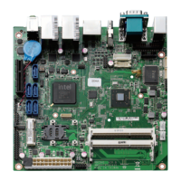
Provides a general introduction to the NEX 605 motherboard, including an image.
Lists the main features and specifications of the NEX 605 motherboard.
Details the technical specifications for CPU, memory, chipset, BIOS, LAN, display, audio, and expansion.
Describes the various I/O ports and connectors available on the motherboard.
Explains the watchdog timer functionality and its programming capabilities.
Details the board dimensions, operating environment, and certifications.
Provides a visual layout of the motherboard, identifying key connectors and components.
Guidance on preparing the workspace and general precautions before working with components.
Explains the function and configuration of jumpers on the motherboard.
Illustrates the physical locations of jumpers and connectors on the motherboard.
Details the jumper for clearing CMOS settings.
Describes the jumper used to select the power mode (ATX or AT).
Explains the jumper for selecting the LVDS backlight power source.
Pin definition for the PS/2 connectors used for mouse and keyboard.
Pin definitions for the COM1 (DB-9) and VGA (DB-15) ports.
Pin definition for the HDMI port.
Pin definition for the dual eSATA ports.
Pin definitions for the first LAN port and USB 0/1 ports.
Pin definitions for the second LAN port and USB 2/3 ports.
Pin definition for the audio connectors (Mic-in, Line-out).
Pin definition for SATA and LAN LED connectors.
Pin definition for the Front Panel control connector.
Pin definition for the SMBus connector.
Pin definition for the Line-in audio connector.
Pin definition for the SGPIO connector.
Pin definition for the USB 6/7 connector.
Pin definition for the USB 8/9 connector.
Pin definition for the LVDS backlight connector.
Pin definition for the COM2 serial port (RS232).
Pin definition for the COM3 serial port (RS232).
Pin definition for the COM4 serial port (RS232).
Pin definition for the Infrared (IR) connector.
Pin definition for the fan connectors.
Pin definition for the RTC battery input connector.
Pin definition for the ATX power supply connector.
Pin definitions for the SATA 2.0 connectors.
Pin definition for the LVDS connector.
Details the pin configuration for the SIM card holder.
Pin definition for the Parallel I/O (PIO) connector.
Pin definition for the Mini-PCIe slot.
Pin definition for the PCIe x4 slot connector.
A diagram illustrating the internal connections and data flow of the motherboard.
Provides the physical dimensions of the motherboard in millimeters.
Explains the BIOS Setup program utility, its function, and how it stores system parameters in CMOS RAM.
Lists the conditions and scenarios that require accessing the BIOS setup program.
Describes how system settings are predefined or automatically detected by the BIOS.
Provides instructions on how to enter the BIOS setup utility during system startup.
Explains the keyboard keys and symbols used within the BIOS setup interface.
Describes how to navigate and access submenus within the BIOS setup utility.
Details the initial screen displayed upon entering the BIOS Setup Utility.
Explains how to view and configure the system's date and time settings.
Indicates the current user's access level within the BIOS.
Configures the Advanced Configuration and Power Interface (ACPI) settings for system power management.
Allows configuration of system wake-up events based on the Real-Time Clock (RTC).
Provides settings for configuring the processor, including Hyper-Threading and Execute Disable Bit.
Option to limit the CPUID instruction return value for compatibility with certain operating systems.
Settings for configuring the Intel Integrated Graphics Device (IGD), including display output.
Configures SATA drive modes (IDE, AHCI, RAID) and port settings.
Settings for managing USB devices, including legacy support and USB 3.0.
Workaround for OSs not supporting EHCI hand-off for USB controllers.
Configures serial and parallel ports managed by the Super I/O chip.
Enables or disables and configures the COM1 serial port.
Enables or disables and configures the COM2 serial port.
Enables or disables and configures the COM3 serial port.
Enables or disables and configures the COM4 serial port.
Configures the parallel port (LPT/LPTE) settings and device mode.
Settings related to the South Bridge chipset features, including power loss behavior.
Enables or disables the Azalia High Definition Audio controller.
Enables or disables the high precision event timer for system timing.
Manages USB device settings specific to the chipset, including EHCI and UHCI controllers.
Determines the default state of the NumLock key upon system boot.
Enables or disables the Preboot Execution Environment (PXE) boot option.
Sets the sequence of boot devices for system startup.
Allows setting or changing the BIOS administrator password for system access control.
Allows setting or changing the BIOS user password for power-on protection.
Saves current BIOS settings and restarts the system.
Exits the BIOS setup without saving any changes made.
Resets all BIOS settings to their factory default values.
Allows bypassing the normal boot sequence to boot from a specific device.
Provides programming instructions and code examples for configuring the Watchdog Timer (WDT).
| Brand | Nexcom |
|---|---|
| Model | NEX 605 |
| Category | Motherboard |
| Language | English |