Copyright © 2014 NEXCOM International Co., Ltd. All rights reserved
27
VMC 1100 User Manual
Chapter 3: Jumpers and Connectors
5
15 11
1
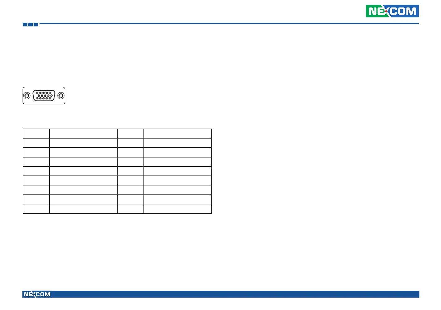
GPIO and Sensor Connector
Connector size: DB-15 port, 15-pin D-Sub
Connector location: CN3
Pin Definition Pin Definition
1 SPEED_1 2 SPEED_2
3 A-VIN0 4 A-VIN1
5 IO_AGND 6 G_IN-1
7 G_IN-2 8 G_IN-8
9 G_OUT-1 10 G_OUT-2
11 G_OUT-3 12 DR_GPS-1PPS
13 DR_GPS-ODOMETER 14 DR_GPS-DIRECTION
15 IO_GND1
** Pin 12, Pin 13, Pin 14 are workable when Dead Reckoning GPS module is used.