L8
L1
...
40
F2
F1
41
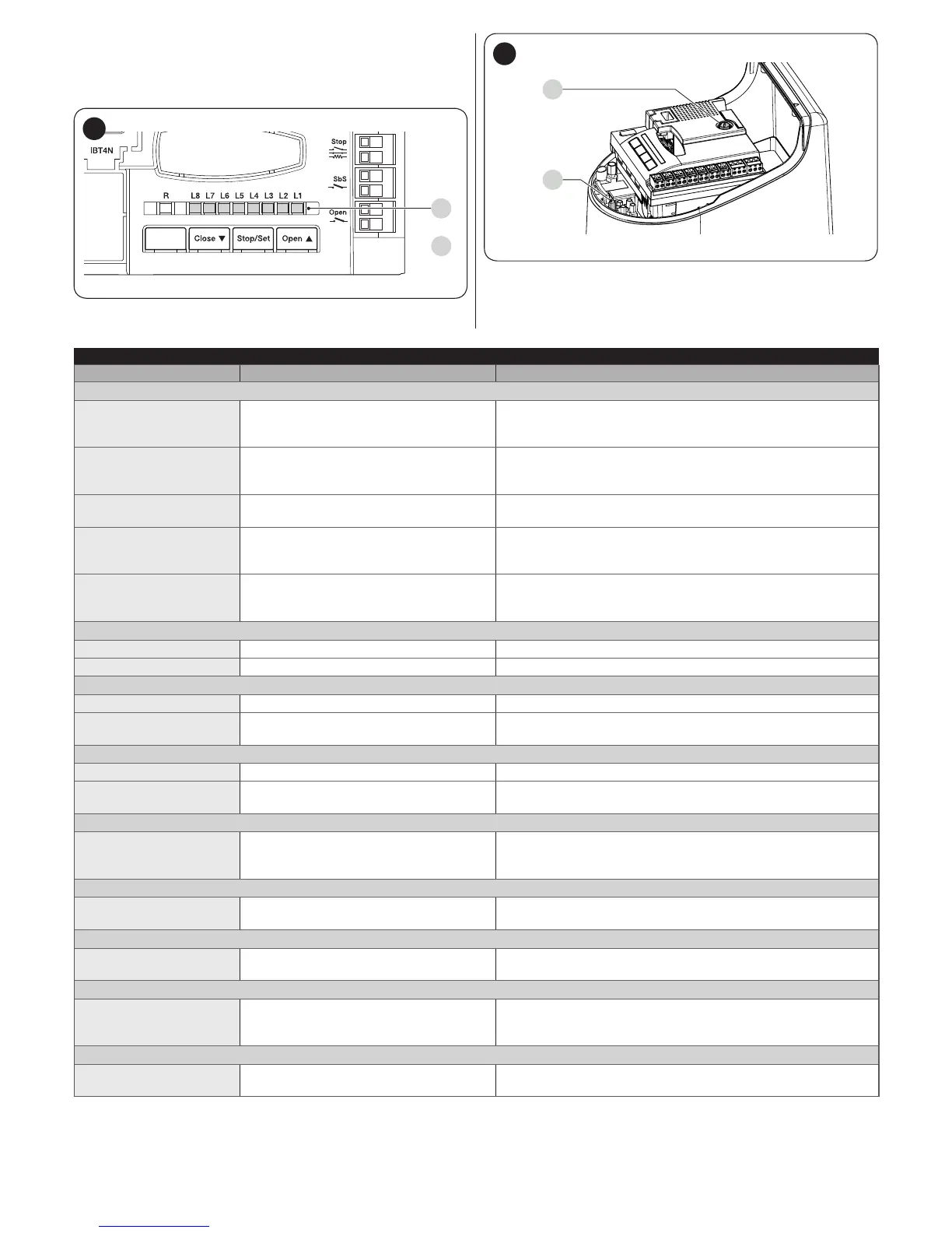
Table 9
TERMINAL LEDS ON THE CONTROL UNIT
Status Meaning Possible solution
BlueBus LED
OFF
Anomaly
Check for the presence of power; check that the fuses are not
blown; if necessary, identify the cause of the fault then replace
them with fuses having the same specications.
On
Serious anomaly
There is a serious anomaly; try switching off the control unit for
a few seconds; if the condition persists, it means that there is a
fault and the electronic circuit board must be replaced.
1 ash per second of the
green LED
Everything normal Normal control unit operation.
2 fast ashes of the
green LED
The status of the inputs has changed
This is normal when there is a change in one of the inputs: SBS,
STOP, OPEN, CLOSE, the photocells intervene or the radio
transmitter is used.
A series of ashes by
the red LED separated
by a 1-second pause
Various
Refer to that shown in “Table 8”.
STOP LED
OFF
Intervention of the STOP input Check the devices connected to the STOP input.
On
Everything normal STOP input active.
Sbs LED
OFF
Everything normal Sbs input not active.
On
Intervention of the Sbs input
This is normal if the device connected to the Sbs input is
actually active.
OPEN LED
OFF
Everything normal OPEN input not active.
On
Intervention of the OPEN input
This is normal if the device connected to the OPEN input is
actually active
LEDs L1 - L2
Slow ashing
Change in the number of devices
connected to the BlueBus or device
learning not carried out
Learn the devices (refer to the “Device learning” paragraph).
LEDs L3 - L4
Slow ashing
The positions of the mechanical stops
were never learned
Learn the mechanical stops (refer to the “Learning of the
mechanical stop positions” paragraph).
LED L5
Slow ashing
Everything normal
The EL output was associated with a function other than
“electric lock” and “courtesy light”.
LED L7
Slow ashing
Everything normal
The SBS and OPEN inputs were associated with a combination
of functions other than “Step-by-Step” and “Partial open 1” or
“open” and “close”.
LED L8
Slow ashing
Everything normal
The FLASH output was associated with a function other than
“warning light” and “open gate indicator”.