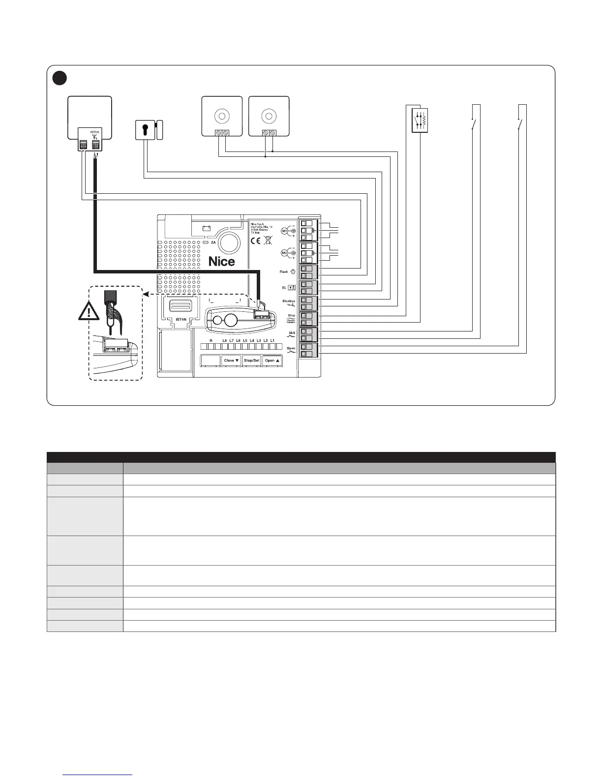
27
4.2.2 Description of connections
Table 3
ELECTRICAL CONNECTIONS
Terminals Description
Flash Output for 12 V (maximum 21 W) warning light or an ELDC warning light [Note 1]
EL Output for 12 Va (maximum 15 VA) electric lock [Note 1]
Bluebus
This terminal can be used to connect compatible devices, which are all connected in parallel with only two wires
carrying both the electric power and communication signals.
Example: EPM, EDSB, ETPB
For further information on the BlueBUS, refer to the “BlueBUS” paragraph.
Stop
Input for devices that suspend or even stop the current manoeuvre; “Normally Closed” and “Normally Open”
contacts or xed resistor devices can be connected by suitably conguring the input.
For further information on the STOP function, refer to the “STOP input” paragraph.
Sbs
Input for devices that control the movement in Step-by-Step mode; it is possible to connect “Normally Open”
contacts.
Open
Input for devices that control the partial opening 1 movement; it is possible to connect “Normally Open” contacts.
M1 output for gearmotor without control unit (HO7224)
M2 output for gearmotor with control unit (HO7124)
1 - 2
inputs for antenna connection (on OXI receiver)
Note 1 Outputs “Flash” and “EL” can be programmed with other functions (see paragraph “Level 1 programming (ON-OFF)“).