ENGLISH – 9
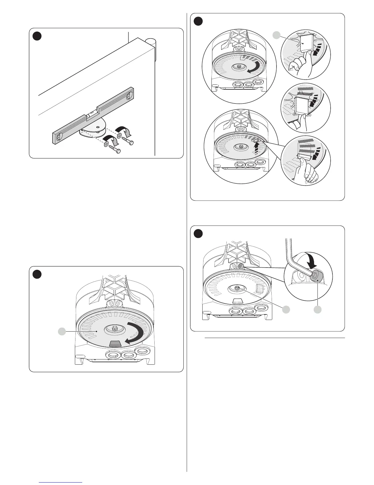
13. fasten the bracket to the gate leaf in the horizontal posi-
tion, using adequate screws (not supplied)
17
14. fasten the arm to the bracket again using the pin and re-
taining ring just removed
15. before locking the gearmotor, adjust the limit switches
(see paragraph “Adjusting the mechanical limit switch-
es“).
3.6 ADJUSTING THE MECHANICAL LIMIT
SWITCHES
To adjust the limit switches, proceed as follows:
1. unlock the gearmotor with the relevant key provided (refer
to the “Manually unlocking and locking the gearmotor”
paragraph)
2. manually move the gate leaves to the fully open position
3. turn the plastic disc (A), located on the lower part of the
gearmotor, moving the slot under the arm to the position
shown
A
18
4. insert the limit switch (B) in the rst available position: try
inserting it as indicated
B
19
5. turn the disc (A) so that the limit switch does not fall and
move the slot towards the position shown in “Figure 18”.
For a ner adjustment, turn the adjustment screw (C)
CD
20
m
If the system has no closing stop on the ground,
the entire procedure must be repeated to adjust the
closing limit switch as well
6. fully tighten the nut fastening the disc (D) to prevent the
latter from turning accidentally.