Summary
Chapter 1 P. 5
Chapter 2 P. 7
Chapter 3 P. 12
Chapter 4 P. 15
Chapter 5 P. 21
Chapter 6 P. 29
Chapter 7 P. 31
Chapter 8 P. 42
AD700E
41
General information
Important safety information
General Information and Ratings
Mechanical Installation
Operation
Parameters
Analog and Digital Input Macro
Configurations
Power Wiring
Chapter 9 P. 48
Chapter 10 P. 50
Modbus RTU Communications
Technical Data
Trouble Shooting
Chapter 11 P. 54
PREVIOUS VIEW
2/2
7
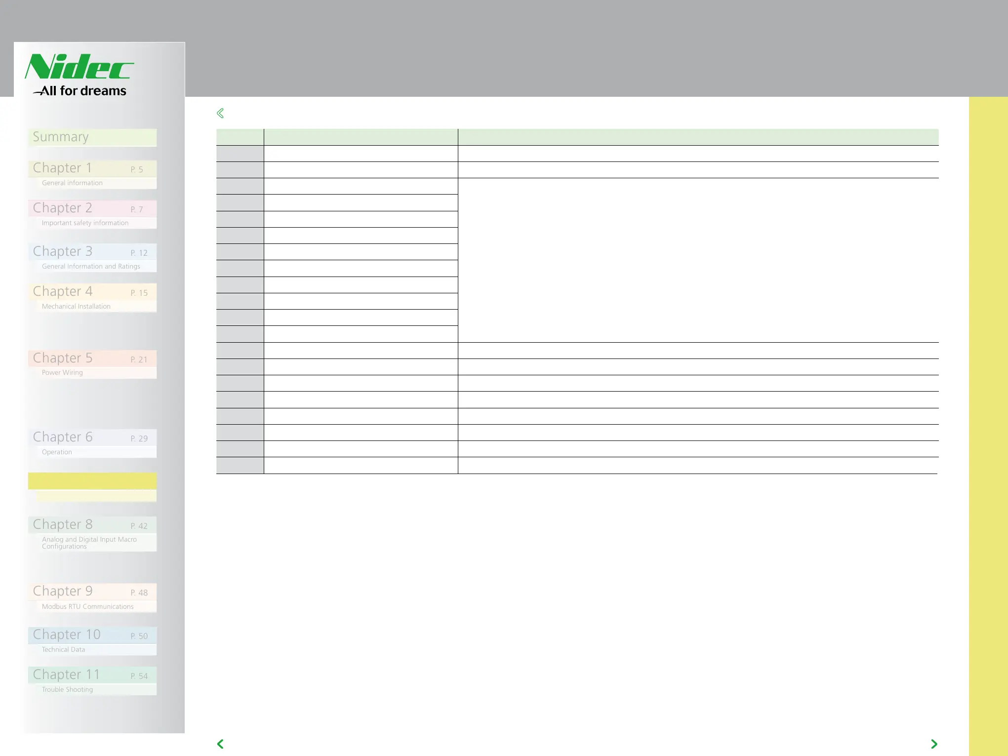
7.4 P-00 READ ONLY STATUS PARAMETERS
Par Description Explanation
P00-31 Motor current Id / Iq Displays the magnetising current (Id) and torque current (Iq). Press UP to show Iq
P00-32 Actual PWM switching frequency (kHz) Actual switching frequency used by drive
P00-33 Critical fault counter – O-I These parameters log the number of times specific faults or errors occur, and are useful for
diagnostic purposes.
P00-34 Critical fault counter – O-Volts
P00-35 Critical fault counter – U-Volts
P00-36 Critical fault counter – O-temp (h/sink)
P00-37 Critical fault counter – b O-I (chopper)
P00-38 Critical fault counter – O-hEAt (control)
P00-39 Modbus comms error counter
P00-40 CANbus comms error counter
P00-41 I/O processor comms errors
P00-42 Power stage uC comms errors
P00-43 Drive power up time (life time) (Hours) Total lifetime of drive with power applied
P00-44 Phase U current offset & ref Internal value
P00-45 Phase V current offset & ref Internal value
P00-46 Phase W current offset & ref Internal value
P00-47 Fire mode total active time Total activation time of Fire Mode
P00-48 Scope channel 1 & 2 Displays signals for first scope channels 1 & 2
P00-49 Scope channel 3 & 4 Displays signals for first scope channels 3 & 4
P00-50 Bootloader and motor control Internal value