SM-Applications Modules & Motion Processors User Guide 15
Issue Number: 4
Safety
Information
Introduction
Installation
Getting
Started
Parameters
DPL
Programming
Communications
Freeze and
Marker
CTSync
Inter-option
Synchronization
Diagnostics
Migration
Guide
Quick
Reference
Index
Please note that SM-Applications Lite, SM-Applications Lite V2 and ST Indexer do not
have these terminals.
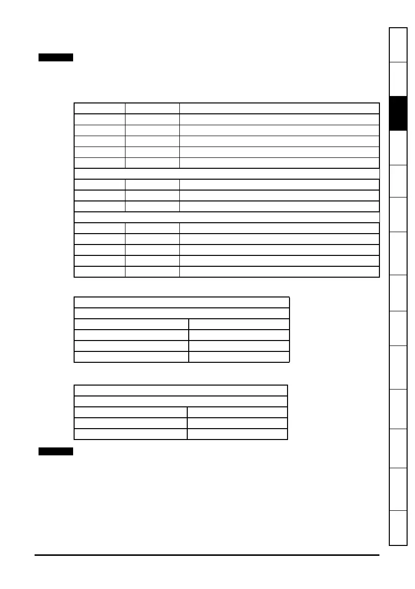
Table 3-1 Module Connectors
Table 3-3 Digital Output Specifications
Please ensure that the drive is off before removing any modules.
Please refer to your installation sheet for more information.
Terminal Function Description
1 0V SC 0V connection for EIA-RS485 port
2 /RX EIA-RS485 Receive line (negative). Incoming.
3 RX EIA-RS485 Receive line (positive). Incoming.
4 /TX EIA-RS485 Transmit line (negative). Outgoing.
5 TX EIA-RS485 Transmit line (positive). Outgoing.
6 CTNet A CTNet data line
7 CTNet Shield Shield connection for CTNet
8 CTNet B CTNet data line
9 0V 0V connection for digital I/O
10 DIO Digital input 0
11 DI1 Digital input 1
12 DO0 Digital output 0
13 DO1 Digital output 1
Table 3-2 Digital Input Specifications
Terminal 10 / Digital Input 0
Terminal 11 / Digital Input 1
Type Positive logic IEC 61131-2
Maximum Input Voltage +/- 30V
Switching Threshold 9.5 V +/- 0.3 V
Load 2 mA at +15 V
Terminal 12 / Digital Output 0
Terminal 13 / Digital Output 1
Type Positive logic when active
Output Voltage 0 / 24V
Nominal max. output 20 mA
When inactive they are effectively floating.
 Loading...