- A ・ -
VBA18001-R.3719.A
logo�Q0440�forGraphic
070518�Gdesign�ito
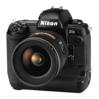
①
Set the AF mode lever (#383) to
"
S
"
.
After pressing the lens release button a few
times, measure the height of the AF coupling
ring shaft (#351).
②
Adjust the height of the AF coupling ring shaft
by the screw (#1597).
③
When the height of the lens release pin becomes
0.4mm, check if the AF coupling ring shaft does
NOT protrude from the bayonet face.
④
After the adjustment, x the screw (#1597) with
the screwlock.
1.7±0.2mm
Bayonet face Lens release pin
Lens release pin
AFTER
adjustment, apply
Screw #1597
#351
Adhesive: Screwlock
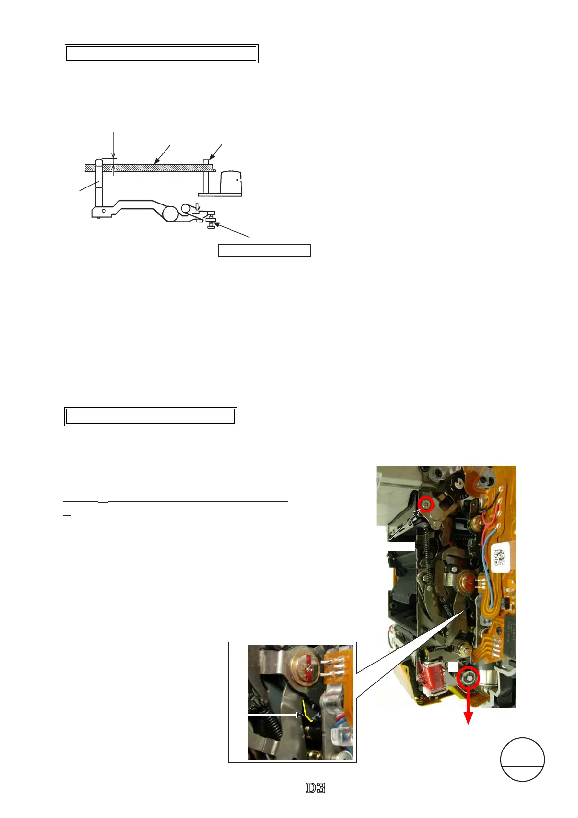
△
(Addition)
1. Lower
①
part for charging.
2. Push
②
all the way to end toward the mount-side.
3.Measure the height of the aperture lever by using the
tool (J18004).
Standard: 3.4 mm
In case the value is out of standard, make the adjustment
by turning the adjustable
screw.
+0.1
-0.05
Height adjustment of Aperture lever
Height adjustment of AF coupling shaft
Dec.28.2007
Changed page
△× 2
△
(Revision)
I base-plate unit #B10071
①
②
Adjustable screw
 Loading...