- A ・ -
VBA18001-R.3719.A
logo�Q0440�forGraphic
070518�Gdesign�ito
Procedure
①
Make temporary assembly of the bottom cover with four screws.
②
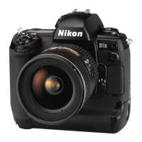
Mount "AF50/1.4D" on the camera, and x them on the tripod horizontally.
③
Connect the camera and PC via cable MC-31 or USB cable.
④
Connect the AC adapter EH-6.
Caution:Be careful NOT to cause a short-circuit at uncovered portions.
⑤
Attach the AE-CCD positioning tool (J63097) to the color viewer (J63070), and turn power ON.
⑥
Keep a 0.7-m distance between the front face of the AE-CCD positioning tool and the reference surface of
the camera. Set the camera AF to manual, and rotate the focus ring to set to "0.7 m".
⑦
Start up the inspection and adjustment software for D3, and select "Inspection and Adjustment for AE CCD
POSITION" then "Set Camera for AE CCD POSITION" to lighten the focus area.
Looking through the viewnder, move the camera so that the focus areas of the camera are with the
outer frames of the AE-CCD positioning tool. (ref. PC screen)
*
Set the camera and AE-CCD positioning tool horizontally.
⑧
Select "Inspection and Adjustment for AE CCD POSITION".
*
Cover the camera with a black cloth, etc, when measured.
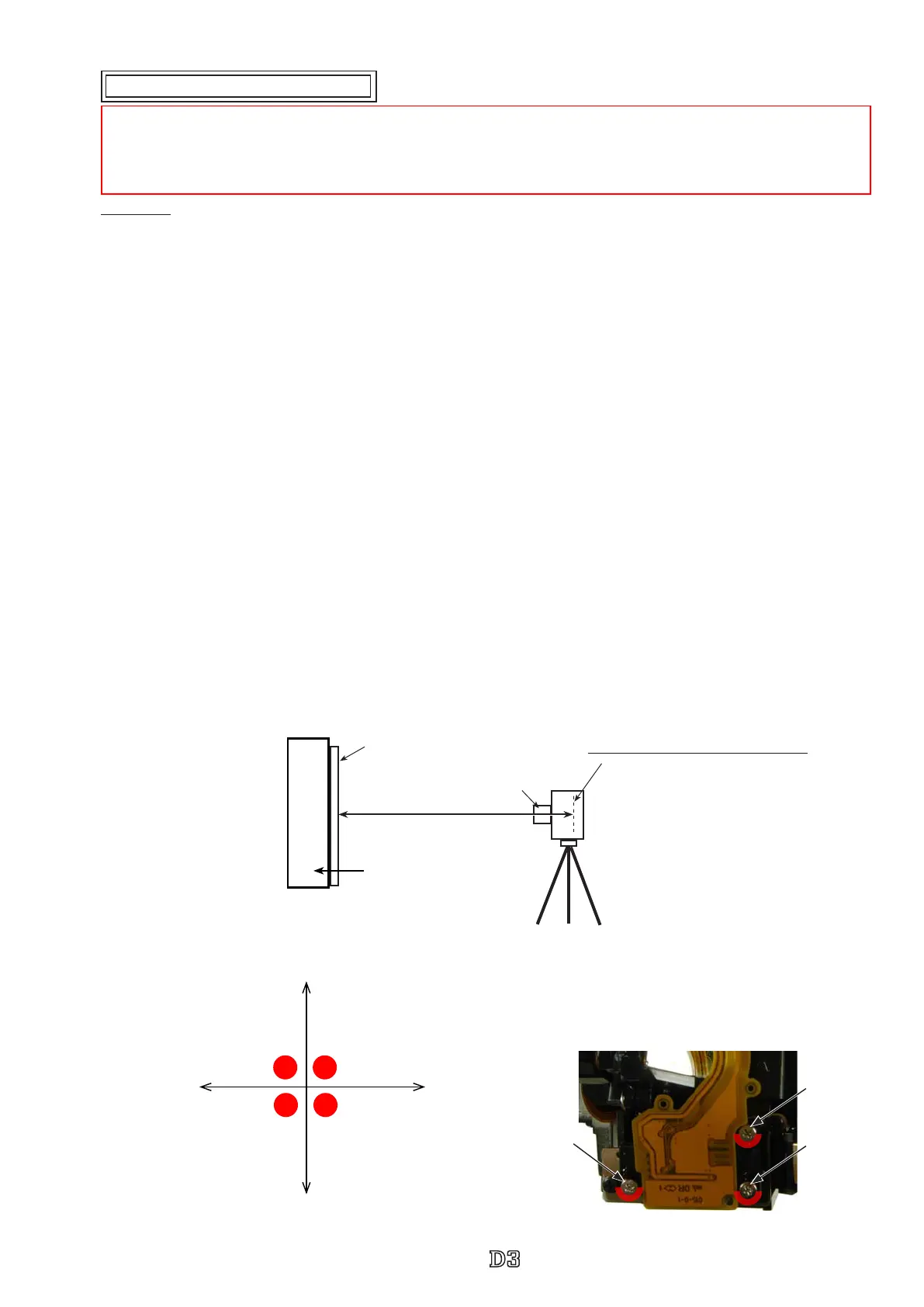
⑨
By following the instructions on PC, adjust the position of AE-CCD with the screws (a and b).
⑩
After conrming that the tilt is within standard, x the three screws with the screwlock.
approx. 0.7
m
AE-CCD positioning tool
(
J63097
)
AF50/1.4D
Attaching surface of the imaging-PCB
Color viewer (J63070)
Reference
→
Reference screw
X-axis direction
→
a: Screw
Y-axis direction
→
b: Screw
X-axis direction
Y-axis
direction
Reference
Screw a
Screw b
Adjustment of AE CCD positioning
*
Under the environment where the AE-CCD positioning is adjusted, use the reference body and conrm results.
・
In case the measured value is out of standard, check whether there is no deviation of the focus area positioning.
・
In case the measured value is out of standard, change the environment of measurements. (e.g. setting place/direction,
room brightness, etc)
Y-axis direction (b)
tightening
Y-axis direction (b)
loosening
X-axis direction (a)
tightening
X-axis direction
(a) loosening
 Loading...