- A ・ -
VBA18001-R.3719.A
logo�Q0440�forGraphic
070518�Gdesign�ito
・
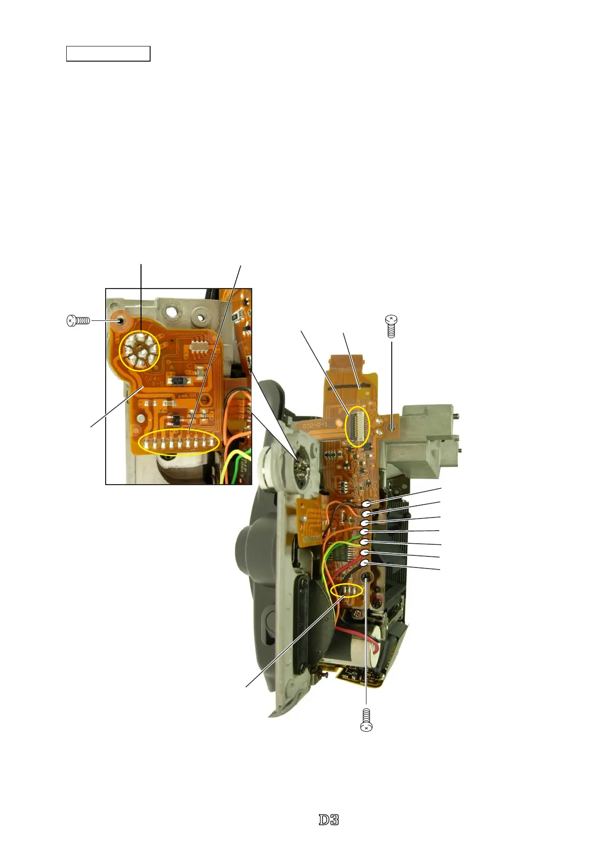
Attach the connection-FPC (#5031).
・
Tighten the screws (#1525 and #1565).
・
Connect the FPC to the connector.
・
Attach the remote terminal FPC (#5032).
・
Tighten the screw (#1503).
・
Make nine each of soldering bridges at two places.
・
Make four soldering bridges.
・
Solder seven wires.
#5031
#1525
Soldering bridge × 4
Black: Lens release SW unit
Orange: Lens release SW unit
Black:AF driving base plate
Red:AF driving base plate unit
Yellow:AF mode change base unit
Green:AF mode change base unit
Orange:AF mode change base unit
#1565
FPC
Soldering bridge × 9
#1503
#5032
Connection-FPC
Soldering bridge × 9
 Loading...