4 Assembly
41
IC Inspection Microscope ECLIPSE L200ND / L200N Instructions
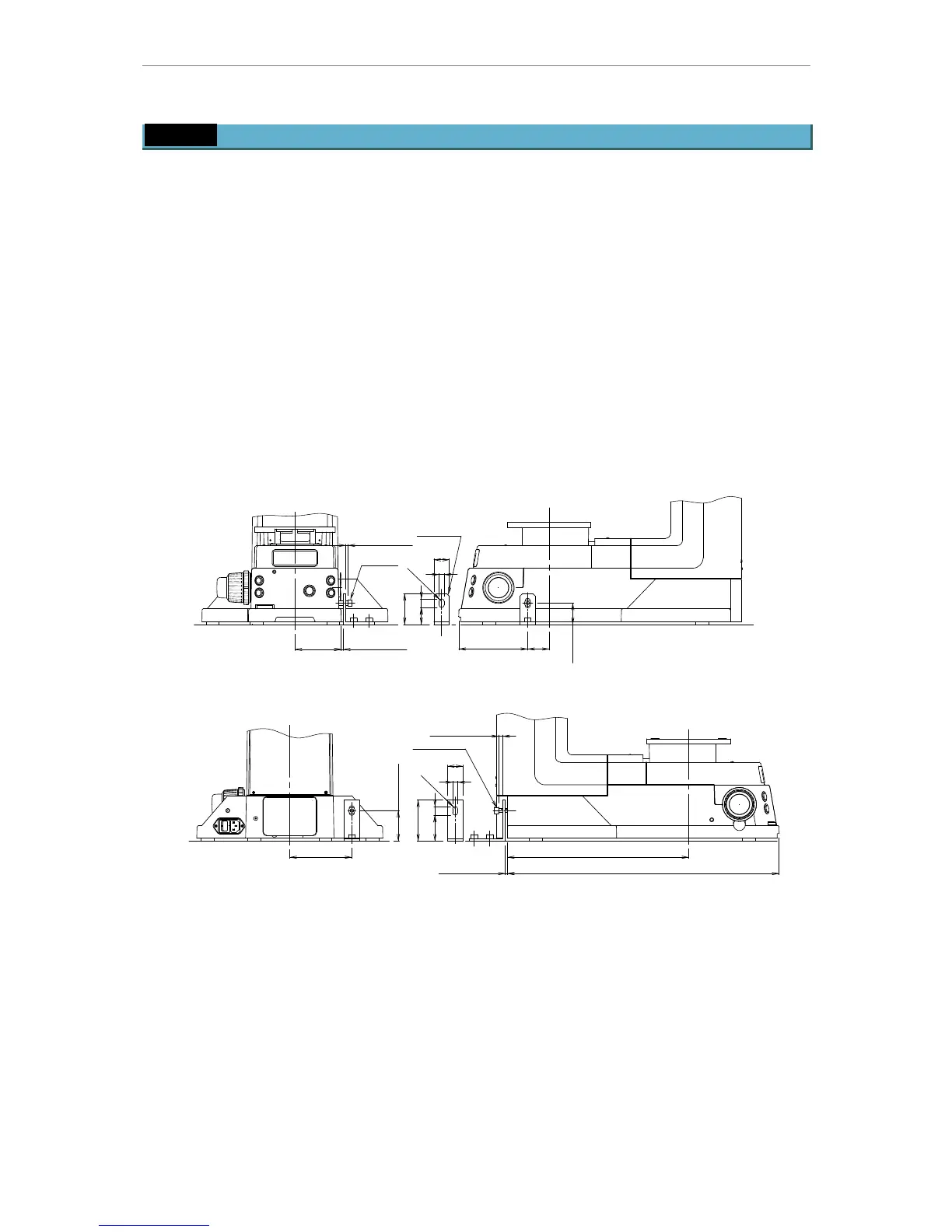
4.11 Seismic restraint
Nikon recommends you to screw securely the microscope on the base to prevent sliding of
the microscope on the base during an earthquake.
1.
Provide two pieces of the angles as illustrated below (the below figure shows the
installation dimensions to the microscope. Installation dimensions to the installation
surface must be decided considering conditions of the installation surface. The material
of the angle must be aluminum alloy and the gauge must be over 5 mm).
2.
Fix the angles on the installation surface using screws.
3.
Turn the bolt through the elongated hole on the angle into the screw hole for carrying
rod on the microscope to connect the angle and the microscope. Use appropriate two
screw holes for carrying rod out of four.
• Provide a gap of a few millimeters between the microscope, angle, and the head of the bolt.
Otherwise, vibrations of the earthquake shake the microscope to interfere observation through the
microscope.
M8 L30
M8 L30
57-61
351
526
120
51 17
10
30
80
2-R5
33 17
10
30
60
2-R5
42133
39-43
90
Figure-48 Installation dimensions
Gap
Gap
Chamfer
Gap
Gap