7210 SAS-D CHASSIS INSTALLATION GUIDE System Overview
Issue: 08 3HE 10087 AAAA TQZZA Edition 01 25
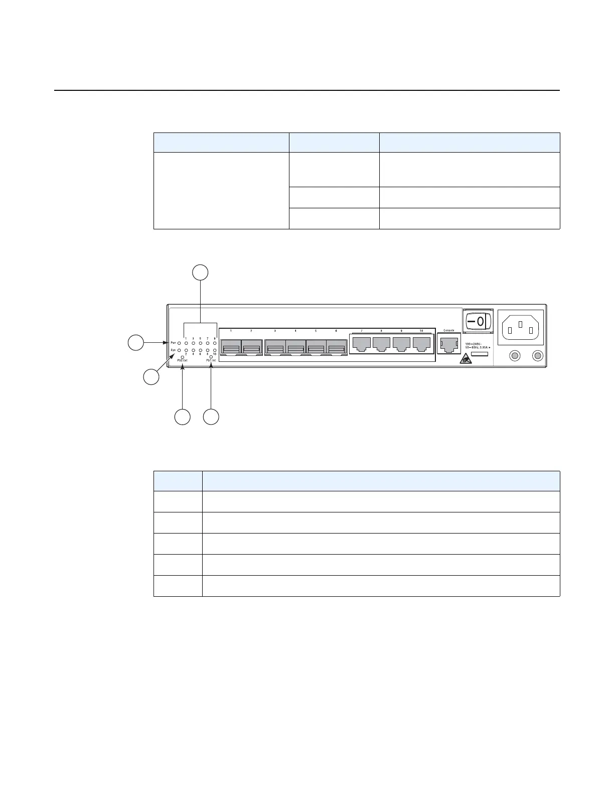
Figure 9 Location of the System and Port LEDs for the ETR Chassis
Table 8 Port LED Behavior
LED Condition Status
1/1/1 – 1/1/6 – SFP ports
1/1/7 – 1/1/10 – Fixed
Copper ports
Green Indicates that the port has a valid
link
Flashing green Indicates activity on the port
Off Indicates that the link is down
Table 9 Location of System and Port LEDs for the ETR
Key Description
1 Power LED
2System LED
3Port LEDs
4 Power Supply Status LED – Integrated Power Supply
5 Power Supply Status LED – External Power Supply

 Loading...