Nokia EM5400 IP Security Platform (IP260 and IP265 Appliances) Installation Guide 11
Figures
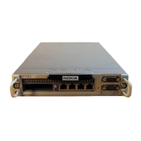
Figure 1 Component Locations Front View . . . . . . . . . . . . . . . . . 21
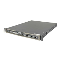
Figure 2 Component Locations Rear View . . . . . . . . . . . . . . . . . 22
Figure 3 Built-In Ethernet Interface Front Panel Details . . . . . . . 22
Figure 4 Pin Assignments for Console and AUX Connections . . 24
Figure 5 Appliance Status LEDs . . . . . . . . . . . . . . . . . . . . . . . . . 26
Figure 6 Installing the Mounting Brackets . . . . . . . . . . . . . . . . . . 30
Figure 7 Single Appliance Installation . . . . . . . . . . . . . . . . . . . . . 31
Figure 8 Power Switch Location . . . . . . . . . . . . . . . . . . . . . . . . . 39
Figure 9 Nokia Network Voyager Reference Access Points . . . . 44
Figure 10 Output Connector for the Ethernet Cable . . . . . . . . . . 49
Figure 11 Ethernet Crossover Cable Pin Connections . . . . . . . . 50
Figure 12 Inserting a PC Card . . . . . . . . . . . . . . . . . . . . . . . . . . . 53
EM5400 IP Security Platform includes IP260, IP265, 50i, 50s Appliances