Nokia EM5400 IP Security Platform Appliance Overview
Nokia EM5400 IP Security Platform (IP260 and IP265 Appliances) Installation Guide 25
Table 3 shows how to match pins at the console or serial connector with
output pins on DB9 or DB25 cables you are using with terminal devices or
other appropriate equipment.
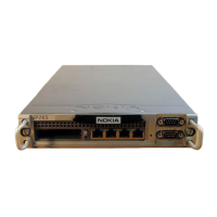
System Status LEDs
You can monitor the basic operation of Nokia EM5400 appliances by
checking their status LEDs. The system status LEDs are located on the front
panel of the appliance, as Figure 5 shows.
Table 3 Pin Assignments for DB9 and DB25 Interface Cables
Console or serial
pin and assignment
DB9 cable output pin and
assignment
DB25 cable output pin and
assignment
Shield (FG) Shield (FG) 1 (FG)
2 (RXD) 3 (TXD) 2 (TXD)
3 (TXD) 2 (RXD) 3 (RXD)
4 (DTR) 6 (DSR) 6 (DSR)
5 (SG) 5 (SG) 7 (SG)
6 (DSR) 4 (DTR) 20 (DTR)
7 (RTS) 8 (CTS) 5 (CTS)
8 (CTS) 7 (RTS) 4 (RTS)
EM5400 IP Security Platform includes IP260, IP265, 50i, 50s Appliances