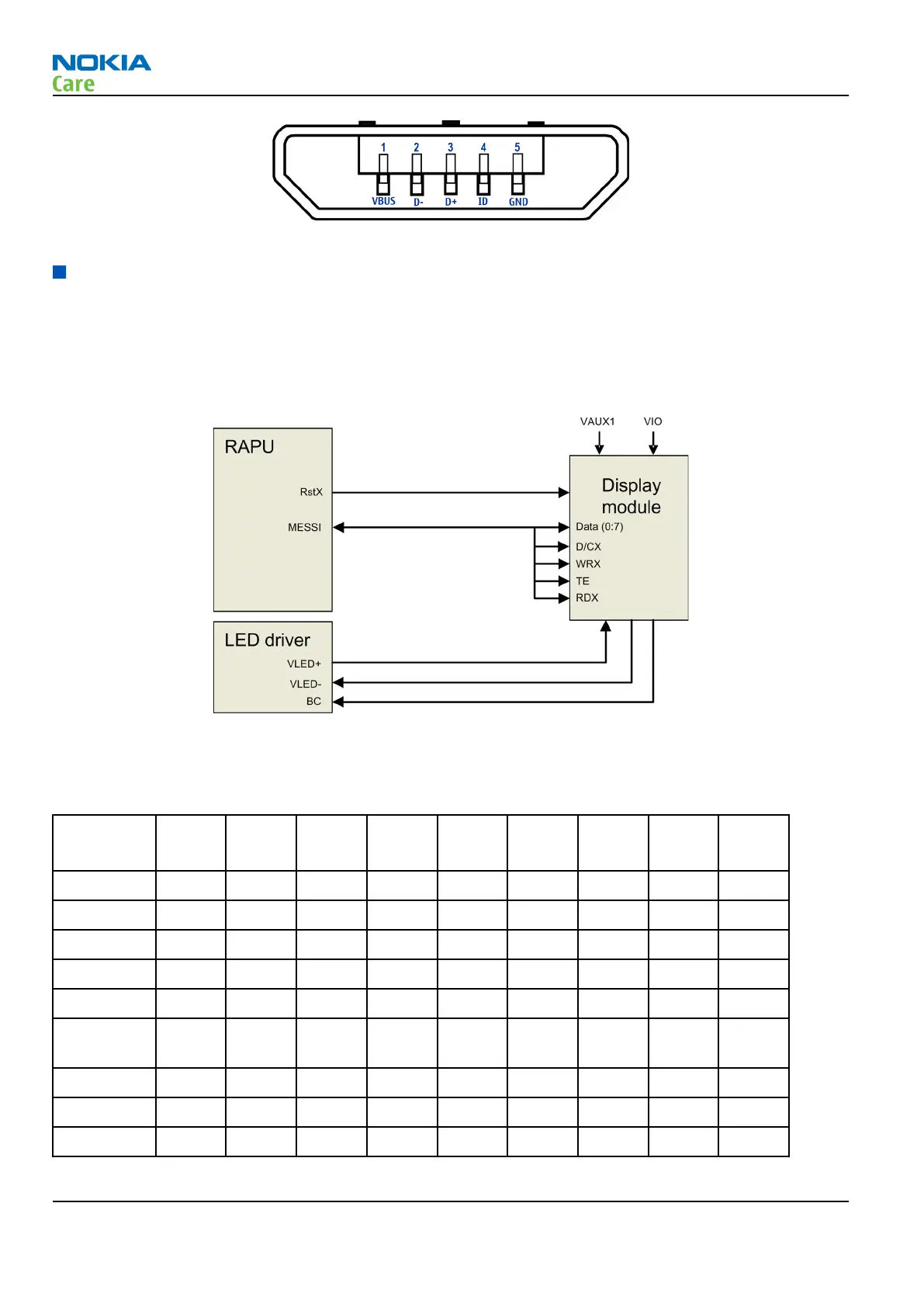
Figure 34 MicroUSB connector
User interface
Display interface
The following block diagram illustrates the display interface. Command signals and transmitted data to the
display module comes directly from RAPU.
Display backlight is provided by an external LED driver.
Figure 35 Display interface
Keyboard interface
Table 10 Key signal matrix
KEY_COL
KEY_ROW
<0> <1> <2> <3> <4> <5> <6> <7> <8>
<0> FN Shift Chr Space N Vol + Space &
<1> Z X C V B Vol - M , ;
<2> A S D F G H J K
<3> Q W E R T Y U I
<4> ? ! CTRL Left Select Right Down S60-L
<5> . : Return Soft-
Left
Up Soft-
Right
S60-R Send
<6> L BS
<7> O P
<8>
RM-632; RM-634; RM-699
System Module
Page 5 – 14 COMPANY CONFIDENTIAL Issue 3
Copyright © 2010 Nokia. All rights reserved.