32
Appendix - Conductivity module MDCD
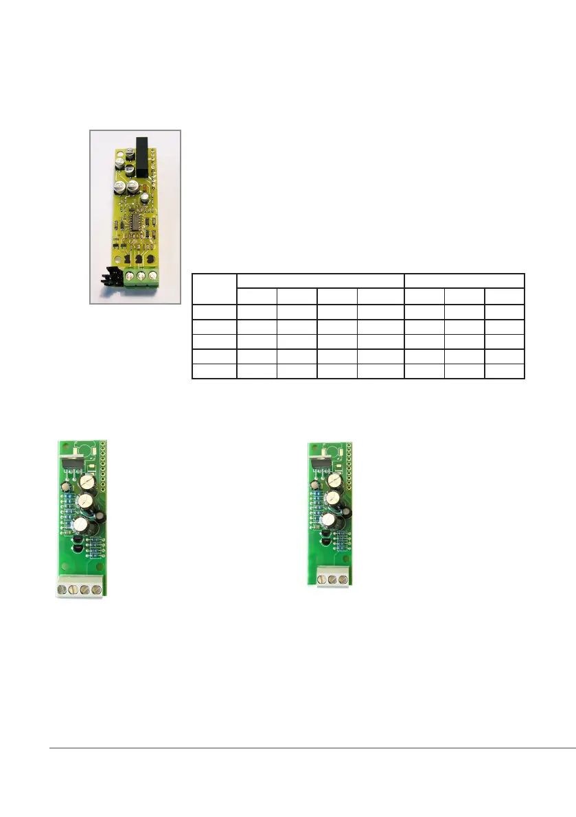
MDCD
Connect probe as follows:
Block n.1 : Shield
Block n.2 : Black (probe)
Block n.3 : Red (probe)
Extra wires for EICDHPTI on mainboard:
6(Green) - 7(Brown)
8(White) - 9(Yellow)
J5
J4
J3
1 2 3
Instrument
scale
PROBE MODEL JUMPERS SETTING
K PlatinUM Graphite Stainless Steel J3 J4 J5
0 - 300.0 uS 0.1 ECDHL/01 x ECDI/01 OPEN CLOSED CLOSED
0 - 3000 uS 1 ECDHL/1 ECDC/1 ECDI/1 OPEN CLOSED OPEN
0 - 30.00 mS 1 ECDHL/1 ECDC/1 x CLOSED OPEN OPEN
0 - 30.00 mS 10 ECDHL/10 ECDC/10 x OPEN OPEN OPEN
0 - 300.0 mS 10 ECDHL/10 ECDC/10 x CLOSED OPEN OPEN
Setup connections according to probe features.
MDIND
1 2 3 4
8 WIRES CABLE:
4 PROBE WIRES
4 PT100 WIRES
Connect 4 probe wires to MDIND module as follow:
Block n. 1 : blue
Block n. 2 : black
Block n. 3 : grey
Block n .4 : red
Connect 4 PT100 wires to mainboard (ref. p. 4) as follow:
Block n. 6 : green
Block n. 7 : orange or pink
Block n. 8 : white
Block n. 9 : yellow
MDECDSIND
1 2 3
ECDS IND PT PROBE
Connect 4 probe wires to MDIND module as follow:
Block n.1 : blue
Block n.2 : green
Block n.3 : red
Connect 4 PT100 wires to mainboard (ref. p. 5)
as follow:
Block n. 6 + 7: white
Block n. 8 + 9 : black
Connect ECDHL PT100 extra wires to
mainboard as follows:
Block n. 6 + 7: white
Block n. 8 + 9: green