4
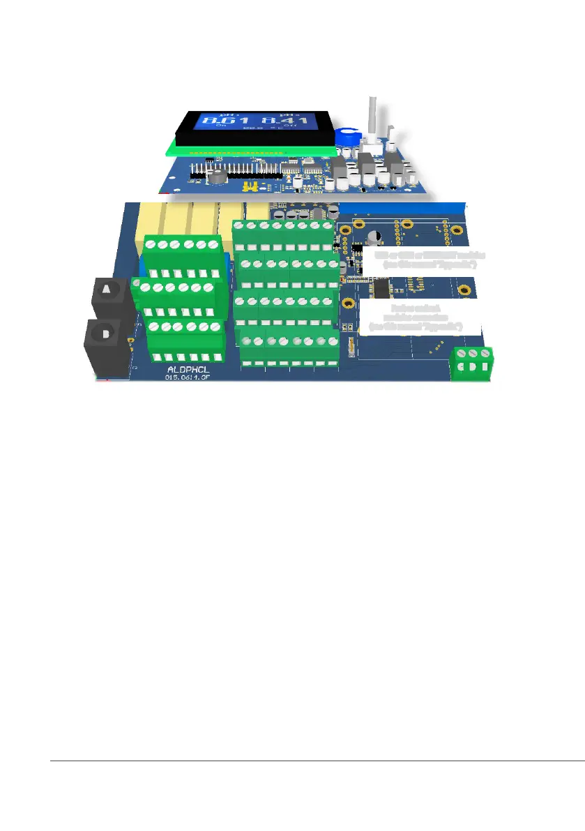
3. Mainboard Connections
Unplug instrument from main power supply then perform connections by following the above picture.
A: Main Fuse (6A T)
B: Instrument Fuse (3.15A T)
C - D - E : Factory reserved +5V
L(Live) - E(Earth) - N(Neutral): 85÷264VAC* or 18÷36VAC* 50/60 Hz *see instrument’s label
1(Live) - E(Earth) - N(Neutral): 85÷264VAC - 5A 50/60 Hz Relay Output “CD Relay 2”. To use with ON/OFF or PWM device
2(Live) - E(Earth) - N(Neutral): 85÷264VAC - 5A 50/60 Hz Relay Output “CD Relay”. To use with ON/OFF or PWM device
3(Live) - E(Earth) - N(Neutral): 85÷264VAC alarm output (MAX 5A)
4(Live) - E(Earth) - N(Neutral): 85÷264VAC “SELF CLEAN” output (MAX 5A)
5(Live) - E(Earth) - N(Neutral): 85÷264VAC “CIRCULATOR PUMP” output (MAX 5A)
6(Green) - 7(Brown) - 8(White) - 9(Yellow): PT100 temperature probe (remove jumper / resistor prior to install probe)
11(-) - 10(+): Standby contact* *for LDSCIND-C version contact is “N.C.” Normally Closed
11(-) - 12(+): CD Level 1 contact
19(-) - 18(+): CD Level 2 contact
14(+ Brown) - 15(Black) - 16(- Blue) - 17(GND): Proximity sensor mod. “SEPR” (dont’ remove jumper between blocks 16 and 17)
21(GND) - 28(+RS485) - 29(-RS485): RS485
24(-) - 25(+): Opto coupled output “CD PULSE”. To use with “IS” , “MF” , “PLUS” series dosing pumps
26(-) - 27(+): Opto coupled output “CD PULSE 2”. To use with “IS” , “MF” , “PLUS” series dosing pumps
31(-) - 32(+): mA Current Output CD
34(-) - 35(+): mA Current Output Temperature
31(-) - 30(+): mA Current Output PID
36(+) ; 37(-): WM Input (max input frequency 500Hz)
L 1 2 3 4 5
E E E E E E
N N N N N N
6 7 8 9 10 11 12 13
14 15 16 17 18 19 20 21
22 23 24 25 26 27 28 29
A
B
MAIN
BOARD
DISPLATY BOARD
30 31 32 33 34 35 36 37
Warning: Connections must be perfomed by qualified and trained personnel only.
⎬
Max resistive load: 500 Ohm
C D E
USB or GSM or ETHERNET modules
(see this manual “Appendix”)
Probes and mA
modules connectors
(see this manual “Appendix”)
(no MODBUS)