19Installation
Nortec GS
2583703_EN_1608
Drainage
The humidier should be connected to a dedicated building drain (recommended) with a minimum
drainage rate of 5.3 gpm (20 L/min). The drain line must allow free and easy drainage.
The building drain pipe should be made of either copper or stainless steel (minimum DIN 1.4301) to
handle discharge water at up to 212 °F (100 °C).
The space in which the humidier is to be installed should have a oor drain connected to the build-
ing drain. However, if a oor drain is not available, a leakage monitoring device must be supplied
to permit interruption of the water supply in case of a leakage. A drain pan is also recommended to
prevent property damage.
Combustion Air
The space in which the humidier is to be installed must have access to a good supply of clean
combustion air at atmosheric pressure. Adhere to appropriate local and national installation regula-
tions for sealed combustion and space air installations.
The maximum temperature of the combustion air supply should be 86°F (30°C).
For additional requirements for sealed combustion and space air installations refer to "Combustion Air
Connection" on page 40.
Exhaust Venting
The space in which the humidier is to be installed must permit routing of exhaust air to the outside.
Adhere to all local and national installation regulations.
For additional requirements for the different types of exhaust vent installations refer to "Exhaust Vent
Connection" on page 43.
Gas Supply
Gas supply to the unit must be equipped with a certied manual gas shutoff valve located in the
immediate vicinity of the humidier.
If black pipe is used, a sediment trap (located between the manual shutoff valve and the unit) must
also be supplied.
A capped 1/8 in NPT test port must be supplied in the gas line immediately upstream from the hu-
midier gas connection.
A union tting must be supplied in the gas line immediately upsteam from the humidier gas connection.
The operating pressure of the gas supply to the humidier must be as listed in Table 7.
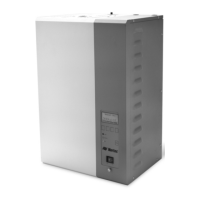
Table 7: Gas Operating Pressure
Gas Type Operating Pressure
Minimum Maximum
Natural gas (North America) 5 in H2O (1.25 kPa) 10.0 in H2O (2.49 kPa)
Propane (North America) 9.0 in H2O (2.24 kPa) 14.0 in H2O (3.49 kPa)
The gas supply line must be sized as listed in Table 8. The pipe connection should have male NPT
threads.
Table 8: Gas Line Size
Model Minimum Gas Line Size Gas Inlet Size (Female)
GS 50 1/2 in (15 mm) 1/2 in NPT
GS 100 1/2 in (15 mm) 1/2 in NPT
GS 150 3/4 in (20 mm) 3/4 in NPT
GS 200 1 in (25 mm) 1 in NPT
GS 300 1 in (25 mm) 1 in NPT
GS 450 1-1/4 in (32 mm) 1 in NPT
GS 600 1-1/4 in (32 mm) 1 in NPT