EasyManua.ls Logo

Nortec GS - Nortec GS 50;100;150;200;300; Wiring Diagrams

Nortec GS
84 pages
Print Icon
To Next Page IconTo Next Page
To Previous Page IconTo Previous Page
Loading...
56 Installation
2583703_EN_1608 Nortec GS
5.11.2 Wiring Diagrams
5.11.2.1 Nortec GS 50/100/150/200/300
Figure 25:
R
6A
Drain
Pump
Fill 1
Stack
Hi-Limit
R
Bk
Float Board
J1
Bk
W
RRY
Blower
Relay
7
8
3
4
51
6
2
N
L
EXTERNAL
INTERNAL
Transformer
24V
On/Off
Switch
1
2
3
4
Gr/Y
S
Legend:
Wire Colors
Bk - Black
Bl - Blue
Br - Brown
O - Orange
Y-Yellow
Gr - Green
Gr/Y - Green &Yellow
R - Red
W - White
L1
L2
Blower 1
M
PWM
PS -
PS +
GND
HS out
1
R
W
Bk
Gr
L1
L2
Blower 2
M
PWM
PS -
PS +
GND
HS out
1
R
W
Bk
Gr
Bk
W
W
R
Bk
Br
Gr
W
R
Bk
Gr
Bk
Gr
W
R
Pressure
Switch
Gas Valve1
Gnd
TH
V2
V1
Ignition
Module 1
Gnd
TH
V2
V1
Ignition
Module 2
Bk
R
Spark
Igniter
Spark
Igniter
Bk
R
R
WRBkBrGr
S
S
YR
Gr/Y
24 VAC
Security Loop
GND
GND
FTBD
CH 1
CH 2
+10 VDC
1 2 3 4 5 6 7 8 9
R
R
R
Y
Y
Gr
Fill 2
Tank
Hi-Limit
Y
Y
R
Tank
Temp
R
Bk
R
Bk
Bk
R
Bk
Gr/Y
Bk
R
Gr/Y
Bk
Gr/Y
Bk
R
CONTROL SIGNAL
CONNECTIONS
PRIMARY VOLTAGE
CONNECTION
EXTERNAL
INTERNAL
Bk Br
RBk
Br
M
R
Bk
R
M
Drain Valve
(optional)
Bk
Gas Valve2
2-Burner
Units Only
M
M
Micro
Pump1
Micro
Pump2
R
Y
Gr/Y
R
Bk
Bk R
Gr
W
2-Burner
Units Only
2-Burner
Units Only
J2 J5
J15
J16
J14
J1
J10
J3
J7
J8
J17
J11
J9
J12
J6
J13
float
pwm1
pwm2
fill 1,2,3
ext
ntc
power
a/p
ignition1
ignition2
RS485-2
RS485-1
24Vout
pmp_fre
drn_blower
digi inputs
DRIVER
BOARD #1
R
J1
J2
PUMP MODULE
CS/NX Models
( on Driver Board)
J18
COM
Remote Fault PCB
NO
NC
Steam
Unit ON
Error
Service
COM
NO
NC
COM
NO
COM
NO
ethernetUSB
comm port
RFB
ACC
J22
LED
J18
display
J17
display
U
U
U
U
J15
J1
J2
J3
J6
J12
J10
J14
J19
J23 J21
J16
INTEGRATED
CONTROL
BOARD
Modbus
Linkup
battery
SIM
card
JP11
JP8
JP7
JP4
Low voltage
terminal strip
Bk
R
3 or 4-Burner
Units Only
Continued on
next wiring diagram
DC
3 or 4-Burner
Units Only
Continued on
next wiring diagram
3 or 4-Burner
Units Only
Continued on
next wiring diagram
A
3 or 4-Burner
Units Only
Continued on
next wiring diagram
B
Gr/Y
Gr/Y
Gr/Y
Gr/Y
Gr/Y
Gr/Y
Gr/Y
JP1
JP2
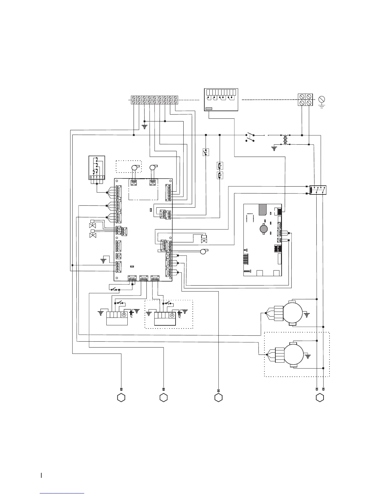
Wiring Diagram - Nortec GS 50/100/150/200/300
JP4 Jumper – for activating the termination resistor for Modbus or BACnet MSTP network.
J6 Connector, Modbus (RS485 interface)
JP7 Jumper – for activating Modbus or BACnet MSTP communication via connector J6.
JP8 Termination, Linkup system
J10 Connector, Linkup

Table of Contents

Related product manuals