53Installation
Nortec GS
2583703_EN_1608
5.10 Humidity Control Systems
5.10.1 Control Device Locations
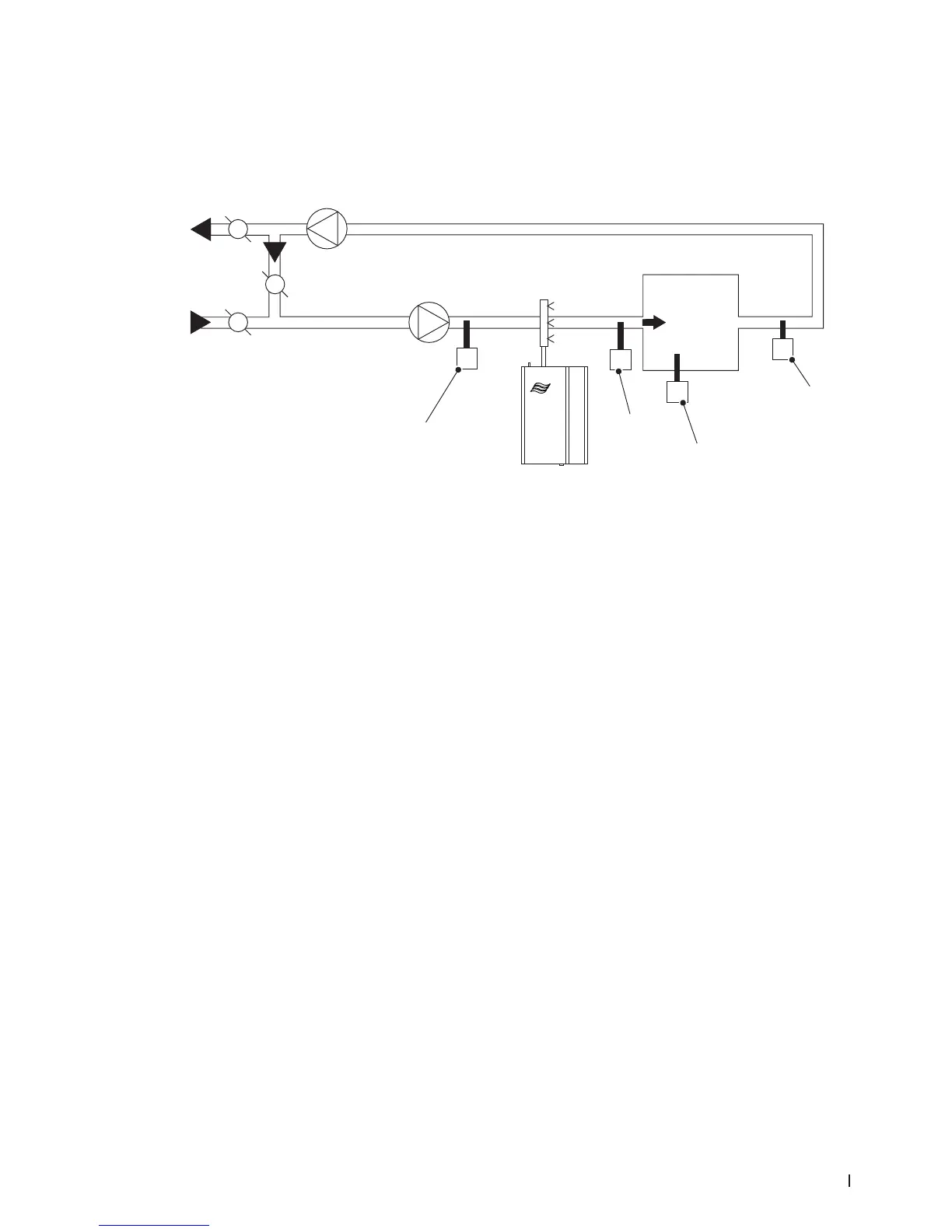
The following schematic describes a potential system setup with respect to control devices. Refer to
Figure 24,
Figure 24:
φ
φ
max
φ
Δp
1
1
2
3
System Setup Schematic
1 Humidistat or humidity sensor
2 High limit humidistat or humidity sensor
3 Switch, air proving
Notes:
• Locate the air proving switch in the same duct as the humidier’s distributor so that it can sense air
ow (or lack thereof).
• Locate the high limit humidistat downstream of the humidier’s distributor so that it can sense a
duct that is over-humidied. Recommended setting is 85% RH. Locate it downstream of the distribu-
tor – at least 5x the absorption distance away. If the absorption distance is not known, locate it at
least 10 feet (3 m) downstream from the distributor. Can be a humidistat (modulating or On/Off), or
a humidity sensor.
• Humidity sensors and humidistats can be modulating or On/Off. Preferred location is in the return
duct, as the supply air is well mixed with the room air at this location. Avoid placing near discharge
diffuser, near doorways, in sunlight, or in airow “dead-zones”.