60 Installation
2583703_EN_1608 Nortec GS
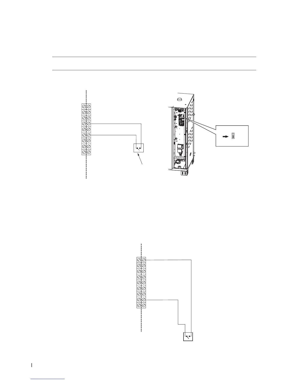
5.11.3.3 On/Off Humidistat Signal
If an On/Off humidistat is used, connect the signal cable to terminal pins "4" and "6" in the low voltage
terminal strip. Refer to Figure 29. Set Control Mode must be set to "On/Off" in the control software – refer
to the Operation and Maintenance Manual.
IMPORTANT! When connecting a 24 VDC On/Off humidistat, jumper JP2 on the driver board must
be set to 24 V (so that pin "6" will output 24 VDC).
Note: By default the jumper JP2 is set to 10 VDC, so that the output can also be used for test purposes.
Figure 29:
1
2
3
4
5
6
7
8
9
24 VAC
Security Loop
GND
GND
FTBD
CH 1
CH 2
+24 VDC
1
10V
24V
JP2
1 2 3
24 V On/Off Humidistat Connection
1 Humidistat, 24 VDC On/Off
5.11.3.4 Full Tank Blowdown Signal Connection
If an external full tank blowdown signal is used, connect the 24 VAC input signal to pins "1" and "8" in
the low voltage terminal strip. Refer to Figure 30.
Figure 30:
24 VAC
INTERNAL
EXTERNAL
24 VAC
Security Loop
GND
GND
FTBD
CH 1
CH 2
+10 VDC
1
2
3
4
5
6
7
8
9
Full Tank Blowdown Signal Connection