59Installation
Nortec GS
2583703_EN_1608
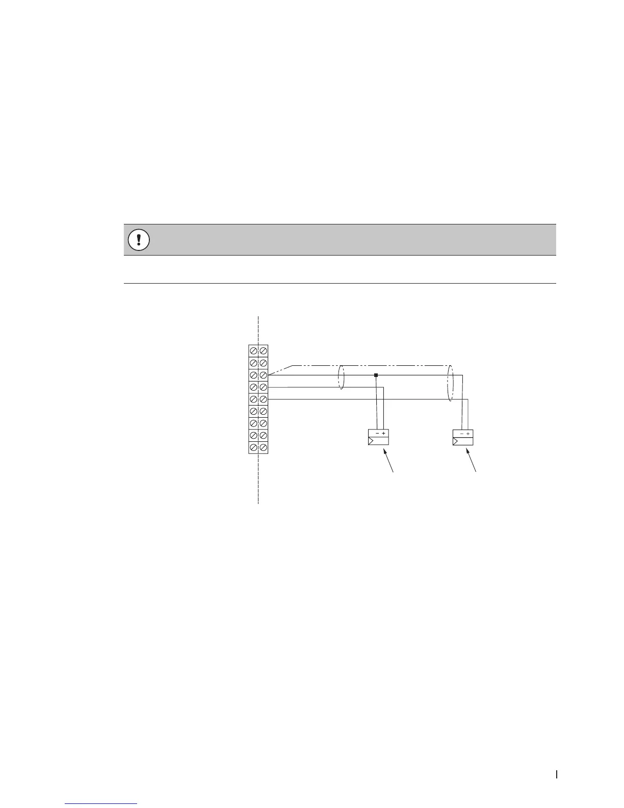
5.11.3.2 Modulating Demand or Humidity Signal
Connect an external humidity sensor input or direct demand modulating input to pins "3" and "4" in the
low voltage terminal strip. Refer to Figure 25 on page 56 and Figure 28. The permissible control signal input
values are shown in Table 17 on page 54.
Do not connect multiple modulating signals to the same modulating input on the humidier. If neces-
sary, connect the second modulating signal to pin "5" and "3", using pin "3" as common. Make sure that
Control Channels is set to "Dual" in the control software to utilize the second modulating signal – refer
to the Operation and Maintenance Manual.
Alternately, transducer signals or demand signals can be written to the humidier via a valid digital com-
munication protocol.
The signal cable must lead into the control cabinet through an appropriate strain relief connector. If a
shielded signal cable is used, connect the shielding to pin "3".
CAUTION!
If the shielding of the signal is already connected to a potential or a grounded conductor, do not
connect it to pin "3".
Figure 28:
1
2
24 VAC
Security Loop
GND
GND
FTBD
CH 1
CH 2
+10 VDC
1
2
3
4
5
6
7
8
9
Modulating Demand or Humidity Signal Connections
1 Modulating demand or humidity sensor signal
2 Modulating high limit demand or humidity sensor signal (additional, for Dual channels)