64 Installation
2583703_EN_1608 Nortec GS
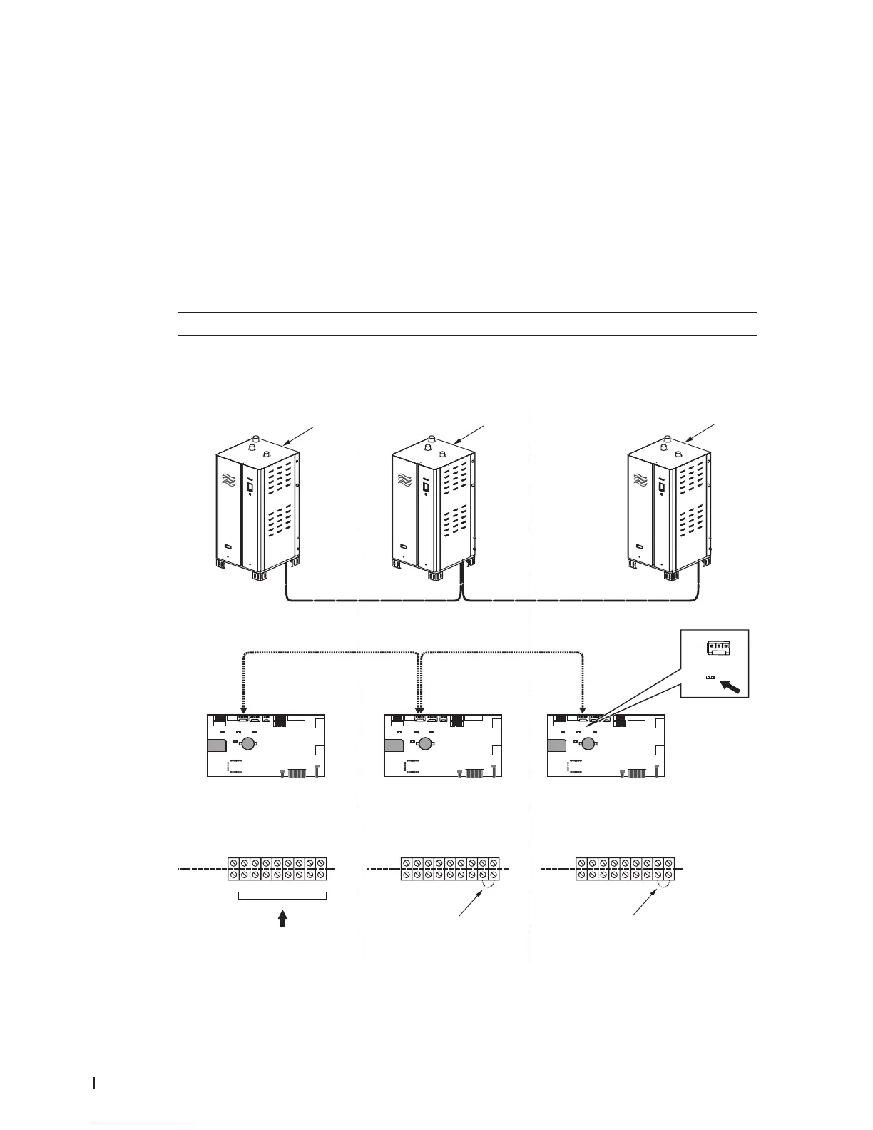
5.11.4 Connecting Multiple Units Using Linkup
The integrated control board in the Nortec GS humidier allows up to four integrated controllers to con-
nect in a "main-extension" conguration using Nortec's Linkup system. All the humidiers within this
setup must share the same environment, and be controlled by one set of control signals connected to
the main unit.
Refer to Figure 34 and connect multiple unit using Linkup as follows:
1. Connect all control signals for the entire Linkup conguration to the low voltage terminal strip in the
main unit.
2. Install a jumper wire between the pins "1" and "2" in the low voltage terminal strip on all extension units.
3. Connect a multi-strand twisted pair shielded cable (18-24 AWG, 120 Ω) between the J10 connectors
on the control board of each Nortec GS humidier in the Linkup system.
IMPORTANT! Do not reverse polarity.
4. Install the termination jumper JP8 in the control board of the last extension unit in the Linkup system.
5. Finally, refer to the Operation and Maintenance Manual to set up the multi-unit conguration in the
control software.
Figure 34:
U
U
U
U
U
U
U
U
U
U
U
U
J6
J10
Linkup
JP8
INTERNAL
EXTERNAL
24 VAC
Security Loop
GND
GND
FTBD
CH 1
CH 2
+10 Vdc
12
3
4
5
6789
24 VAC
Security Loop
GND
GND
FTBD
CH 1
CH 2
+10 Vdc
12
3
4
5
6789
24 VAC
Security Loop
GND
GND
FTBD
CH 1
CH 2
+10 Vdc
12
3
4
5
6789
4
4
All inputs
1
2
3
Multi-Unit Linkup Connections
1 Main unit (all control signals to unit)
2 Extension unit #1 (no control signals to unit)
3 Extension unit #X (no control signals to unit)
4 Jumper (on all extension units)