NTI ENTERPRISE ENVIRONMENT MONITORING SYSTEM
10
Sensor Attachment
Connect the desired sensors (sold separately) to the available ports on the ENVIROMUX. Sensors come with one of two
connection methods, RJ45 and individual wires for terminal connection. This section explains both methods of connection.
Configuration of these sensors will come later in this manual.
RJ45 Sensor Ports
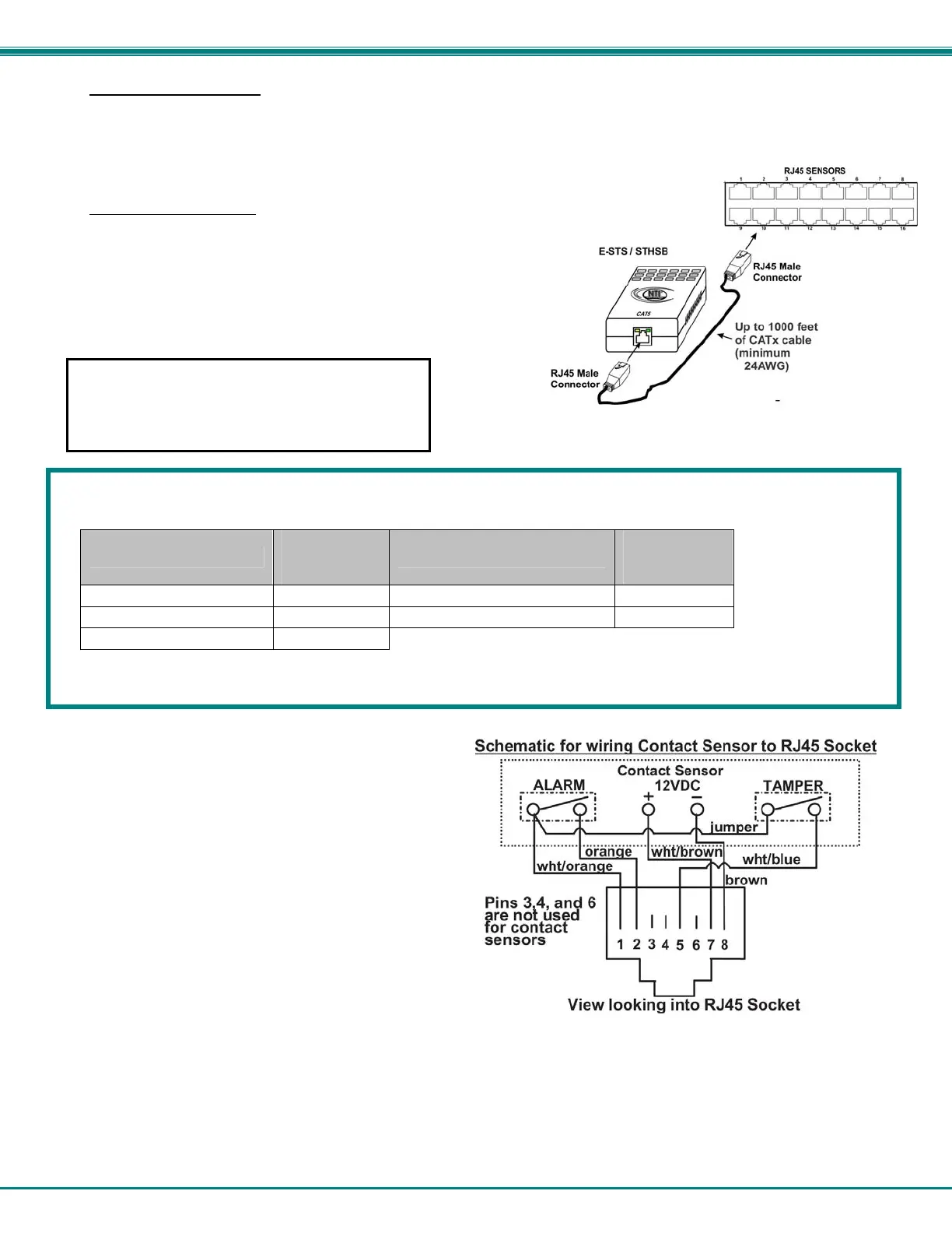
1. Connect each external sensor having an RJ45 male connector on it
(E-STS, E-STHSB, E-LDS) to one of the female connectors labeled
"RJ45 Sensors" on the ENVIROMUX. Male connectors should
snap into place. Cables may be up to 1000 feet in length. See
page 130 for wiring specification and pinout.
Note: It is very important to locate the temperature and/or humidity
sensors away from ventilation sources and fans.
Figure 7- Sensors connected by cables with RJ45 connectors
The RJ45 SENSORS ports can be used to connect a variety of sensors. Specifically on the E-16D, the combined power load of
all 12VDC sensors on each row of ports (ports 1-8 is one row and ports 9-16 is the second) cannot exceed 500mA per row.
Some sensors use more power than others. The table below provides the top power users:
Sensor
12VDC Power
Consumption
in mA
Sensor
12VDC Power
Consumption
in mA
E-S420MA-24V 130 E-ACLM-V 70
E-ACLM-P 130 E-S5VDC(-5V) 100
E-EDR-SF 200
Caution: Be careful not to overload the E-16D as failure may occur and damage to the ENVIROMUX may result.
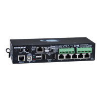
2. Some sensors do not have RJ45 connectors on them
and instead have terminal blocks. These can either be
connected to the "DIGITAL IN" connectors or they can
be terminated and plugged into the remaining RJ45
connectors (see figure-right ). (The illustration uses
CAT5 patch cable to make cable connection easy.)
Some examples of these sensors include E-IMD, E-IMD-
CM, E-VSS, E-SDS, and E-GBS. Cables may be up to
1000 feet in length.
Note: For sensors requiring 5VDC power source,
connect the wht/brown wire to pin 4 instead of pin 7.
All contact sensors can be wired in this way and use the
RJ45 sensor ports instead of the Digital In terminals if
desired.
Figure 8- Contact sensor wired to RJ45 socket
If CATx cabling will be installed near sources of EMI
(electric motors, light ballasts, etc) use shielded
cable to reduce the introduction of noise to the
circuits. Otherwise, communications between the
sensor and ENVIROMUX may be unreliable.