1.
2.
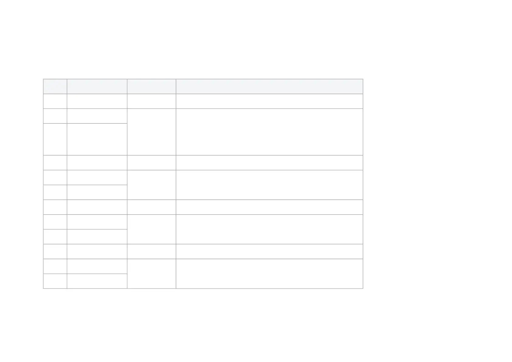
CABLINE-CA II PLUS Connector - Component Side
The below table provides pins description of the CABLINE-CA II PLUS connector mounted on the controller’s component side.
Pin # Pin Name Pin Direction Description
1 GND Ground
2 PCIE_REF- CLK1_P NA PCIe Reference Differential Clock. Not Connected (default)
PCIe separated clocking default scheme
Assembly option to support PCIe shared clocking scheme, then:
For system Controller mode, REFCLK will be output
For system NIC mode, REFCLK will be input
3 PCIE_REF- CLK1_N
4 GND Ground
5 HSO_15N
Input BlueField Card PCIe RX to Carrier Board PCIe TX
6 HSO_15P
7 GND Ground
8 HSO_14N
Input
BlueField Card PCIe RX to Carrier Board PCIe TX
9 HSO_14P
10 GND Ground
11 HSO_13N
Input
BlueField Card PCIe RX to Carrier Board PCIe TX
12 HSO_13P