Clock calculator design
MPC5777C Clock Calculator Guide, Rev. 1, 12/2018
NXP Semiconductors 11
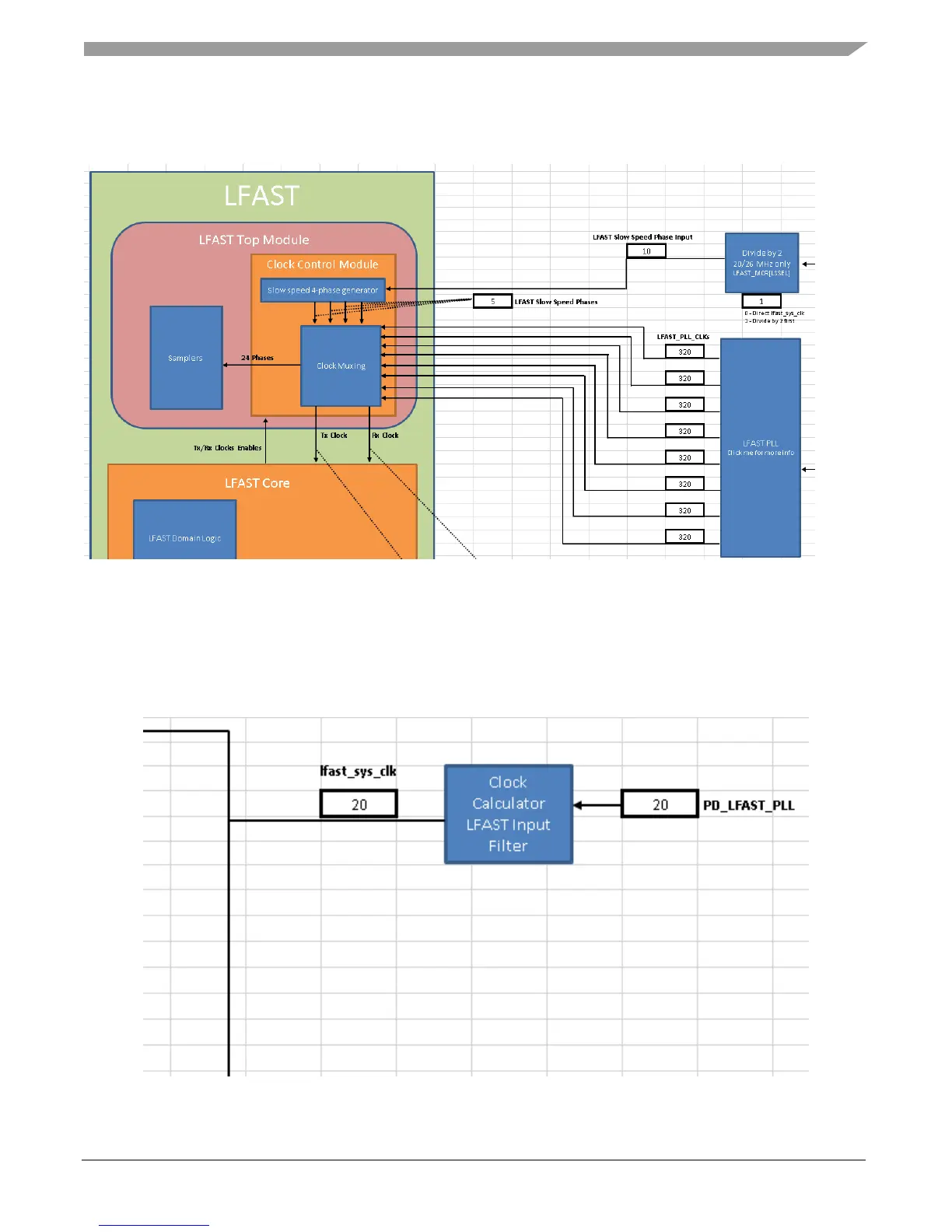
supports a low-speed mode as well as a high-speed mode. This tool allows the user to select between
the two modes. Below is a screenshot of LFAST clocking.
Figure 13. LFAST block diagram
Since the LFAST signal must be generated from an input clock of 10 or 20 MHz, this tool blocks any
input from the signal RF_REF other than these two values. RF_REF can technically be set to any value,
but the signal goes through the clock calculator’s LFAST Input Filter block to become lfast_sys_clk,
which in turn is the signal that gets fed into the LFAST PLL and phase generators, as shown in the
following figure.
Figure 14. LFAST clocking input filter

 Loading...


