Clock calculator design
MPC5777C Clock Calculator Guide, Rev. 1, 12/2018
NXP Semiconductors 13
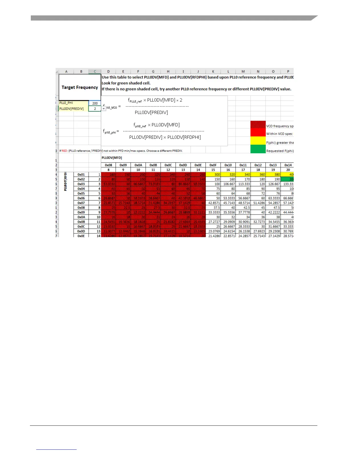
shaded in green; values that exceed the desired frequency, but are within MPC5777C hardware
specifications are marked in yellow; and frequencies that exceed the MPC5777C hardware specification
are colored red. Below is a screenshot of the reference table for PLL0_PHI.
Figure 16. PLL0_PHI Reference table
2.9.
Summary
Almost all blocks populating this clock calculator represent real register fields in silicon. The Summary
tab collates all the information from the rest of the clock calculator into a list of register values, a
screenshot of which is shown in Figure 16. The values in the register summary are interactive, updating
automatically when the associated block is changed. Registers listed within Summary are only the ones
whose values are affected by clock configuration, not every single register available in the chip.

 Loading...


