Clock calculator design
MPC5777C Clock Calculator Guide, Rev. 1, 12/2018
12 NXP Semiconductors
If RF_REF is 10 or 20 MHz, lfast_sys_clk is the same; otherwise, lfast_sys_clk is 0. MPC5777C does
not actually filter RF_REF the way this tool does. The purpose of the LFAST Input Filter block is to
simulate how the user can technically set RF_REF to any value, but the resulting LFAST output would
be unusable. Therefore, if a user were to enter an invalid input frequency (i.e. not 10 or 20 MHz), all
subsequent frequencies would be 0, and the user would know to change the input.
2.7.
PLLx
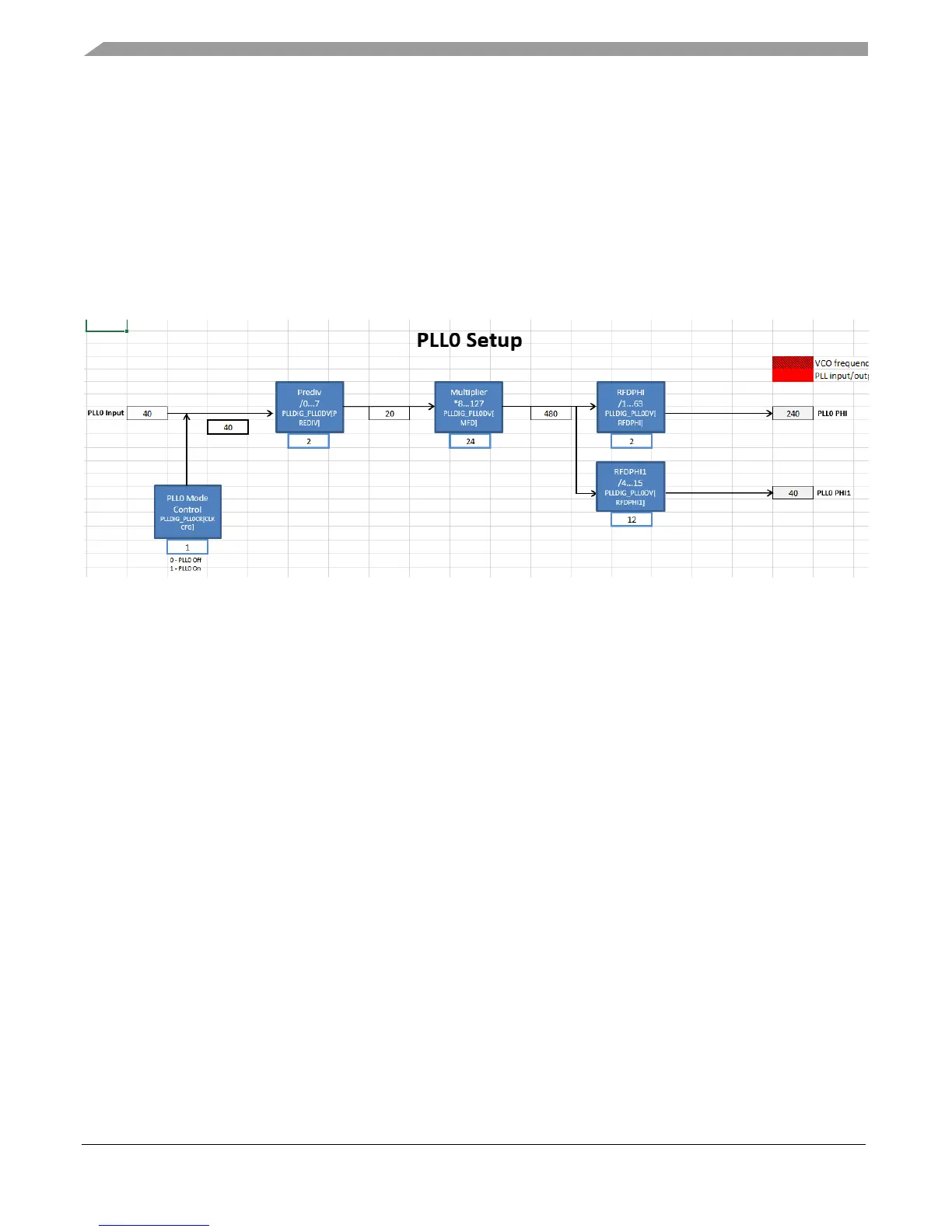
PLL0 and PLL1 are visual abstractions of the PLL digital interface, as shown in the figure below.
Figure 15. PLL0 control
The input source of PLL0 and PLL1 are selected by the PLL0 Clock Selector and PLL1 Clock Selector
blocks in the Tree tab, respectively. Then, from the source, the dividers and multipliers located in the
PLL0 and PLL1 tabs are set in order to achieve the PLL output frequencies. The PLL output frequencies
are in turn propagated to the PLLx_PHIn clock domains in the Tree tab.
2.8.
Reference tables (pll0_phi, pll0_phi1, and pll1_phi)
The three tabs pll0_phi, pll0_phi1, and pll1_phi are reference tables for the user to find the appropriate
PLL dividers and multipliers to achieve the desired PLL frequency. There is a tab for each PLL output
because input frequencies and the range of acceptable divider/multiplier values differ between each
other. However, they all follow the same setup. Note that Columns A, B, and C of these tabs are frozen
so if the table looks cut off, just scroll left or right.
PLL frequencies are calculated from a reference frequency, a reference divider (RFD), a multiplier
(MFD), and in PLL0, a prescaler (PREDIV). The PLL reference is not manually configurable because
there is a finite number of input values the PLL can take. For example, PLL0 can only reference either
the 16 MHz IRC or the 8-44 MHz XOSC. PLL reference therefore comes from the Tree tab. Configure
PLL0 Clock Selector and PLL1 Clock Selector in Tree for PLL0 and PLL1, respectively. Once the PLL
reference frequency is configured, enter the desired PLL output frequency. Also, enter the PREDIV
value when using PLL0_PHI or PLL0_PHI1. The reference table will then calculate the output
frequency for each MFD and RFD setting. Like in the other sections, frequencies are color-coded to
define which values are valid and which are not. Shading will change automatically once the output PLL
frequencies are calculated. MFD and RFD settings that achieve the exact desired frequency will be

 Loading...


