Clock calculator design
MPC5777C Clock Calculator Guide, Rev. 1, 12/2018
6 NXP Semiconductors
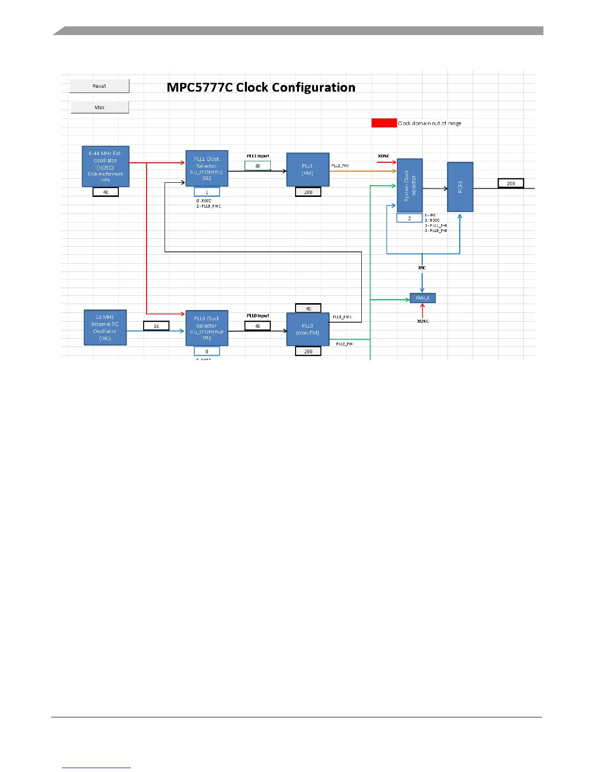
Figure 6. Clock calculator Tree
The flow of the diagram generally goes from left to right. On the left are the MPC5777C clock sources
and on the right are the clock domains. MCU modules run on one or more of these clock domains.
Clock domain frequency values are displayed in the outlined cells next to their labels. Most cells are not
meant to be written to; their values are dependent on the frequencies of preceding steps in the clock tree.
Take FM_PER_CLK, for example: its value is sourced from either the system clock, which in turn
comes from either the IRC, XOSC, PLL0_PHI, or PLL1_PHI. Now look at the XOSC block. XOSC
depends on the settings from the Oscillator Control tab. So all clock domains ultimately derive from a
few select inputs. The IRC is always on at 16 MHz, PLL0_PHI and PLL1_PHI are configured in the
PLL0 and PLL1 tab, respectively. The system clock selects from these four clock sources by selecting
the value of the System Clock Selector block. Then finally the selected signal is divided by the
FM_PER_CLK prescaler value. It is important to note, though, that the user input for the divider field is
not the desired divider, but the bitfield value that one would have to enter to achieve the desired divider.
Some divider blocks like FM_PER_CLK’s, provide a dropdown list with textbox description
underneath. Others support too many input values to be put into a list. The user must provide the proper
bitfield value, not the desired divisor. That is why such blocks are labelled something like
“/(1+(0…63))” rather than simply “/1…64”. The user provides a value between 0 and 63, to which the
hardware automatically adds 1 to calculate a divider that is between 1 and 64.
Tree also features two buttons, Reset and Max. They only function when macros are enabled. Clicking
on these buttons with macros disabled will return an error. If macros are enabled, the Reset button will
set all blocks to their reset value, as described in the reference manual. The Max button sets all blocks in
this tool to values that configure the system and auxiliary clock domains to their respective maximum
allowable frequencies. Below is a screenshot of the buttons.

 Loading...


