Page: 102
Service Guide ML390/391
Chapter 4 Failure & Repair Analysis
4.8.06 Operator Panel Board
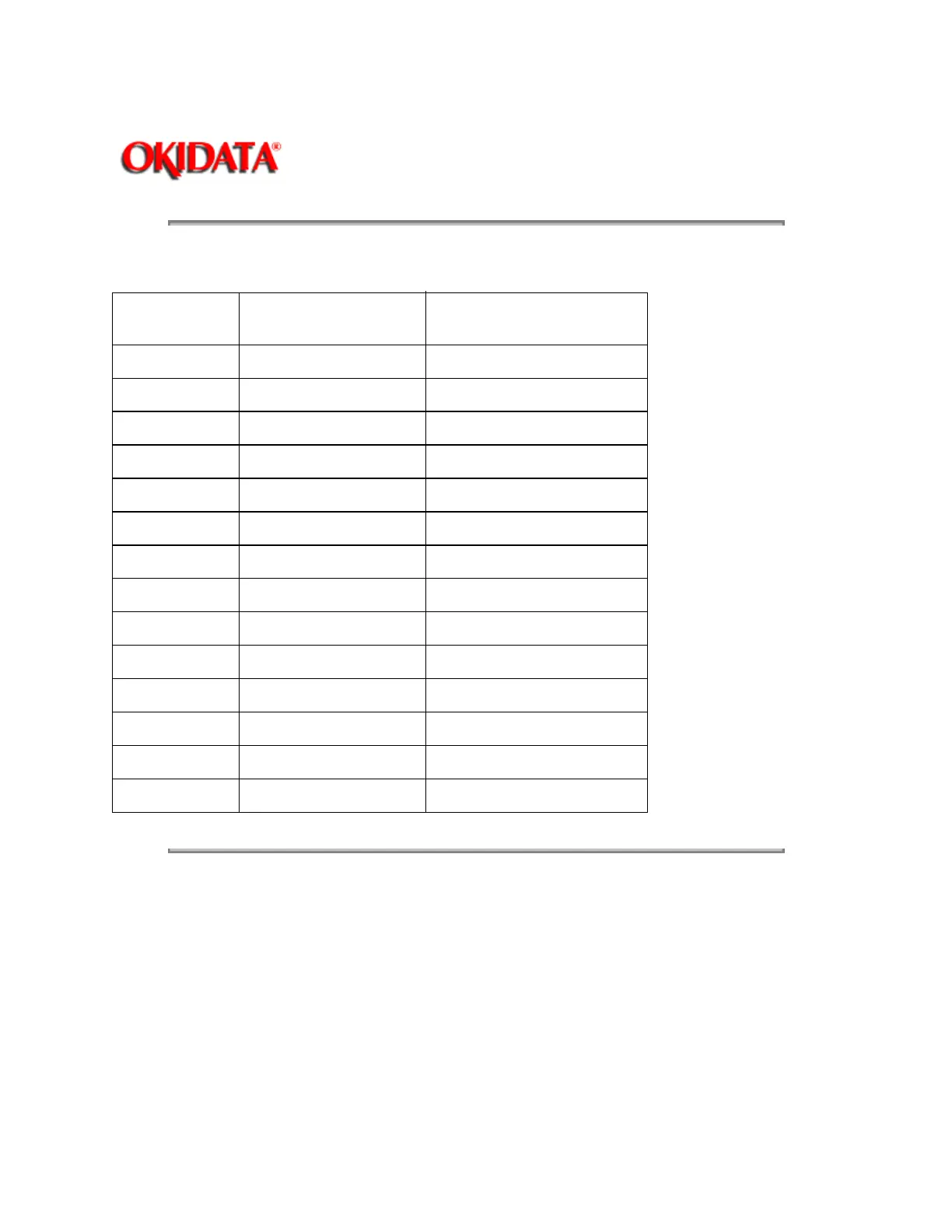
Name
Signal Name Connection (Refer to
Interconnect Diagram)
F
Op Panel SEL 3
MODE 4
LF 5
FF 6
PARK 7
TOF 13
PRINT 10
FONT 11
CHAR 12
SD CLK 14
SD 2
+ 5 V 1,15
0 V 8,9
Copyright 1997, Okidata, Division of OKI America, Inc. All rights reserved. See the OKIDATA Business
Partner Exchange (BPX) for any updates to this material. (http://bpx.okidata.com)