19
9.2 Alarm Icons and meanings
LEO can display different alarms, which are identified by the Alarm Icons displayed on the Homepage
during an alarm condition.
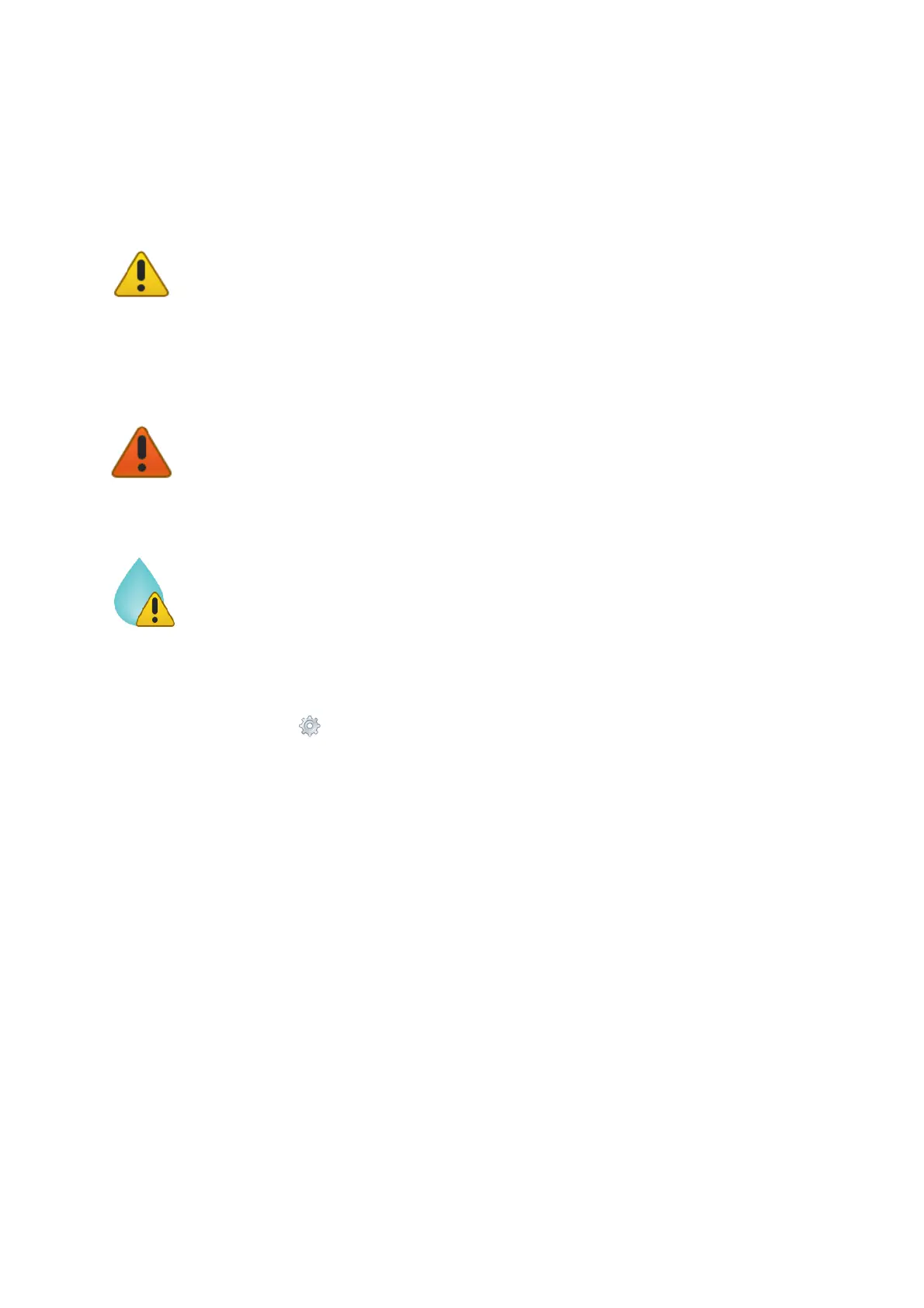
The Yellow Warning Alarm Icon (15 in Figure 19) indicates that the current CO2 or O2
value is out of the range defined in the alarm subpage (see paragraph 9.3.4) during the
Transient Time. The meter doesn’t trigger in Alarm and no action is needed. As soon as the CO2
or O2 value is within the defined range, the Yellow Warning Alarm Icon disappears. If after the
Transient Time the CO2 or O2 value is still out of the range defined by the operator, the Yellow
Warning Alarm Icon changes to Red Warning Alarm Icon.
Tip ► If the temperature sensors are connected to LEO, the Yellow Warning Alarm Icon
appears next to T1 and/or T2 during an alarm condition.
The Red Warning Alarm Icon indicates that the current CO2 or O2 value is out of the
range defined in the alarm subpage (see paragraph 9.3.4) after the Transient Time. The meter
triggers in Alarm.
Tip ► If the temperature sensors are connected to LEO, the Red Warning Alarm Icon
appears next to T1 and/or T2 during an alarm condition.
The Humidity Alarm Icon indicates that the current humidity value in LEO is higher than
80% (for example the Moisture Trap is full). The meter triggers an Alarm. The Alarm Icon
disappears when the humidity returns to a value lower than 80%. This alarm is always active
during all type of measurements. If the alarm occurs during a measurement in Aspiration Mode,
stop the Pump. Failing to do so will expose the CO2 O2 sensor to moisture damaging it.
9.3 Settings
Press on Settings icon (see Figure 20 a) to enter the Settings menu, as shown in Figure 20 b. The
settings menu has eight items:
1. Device. See paragraph 9.3.1
2. Calibration. See paragraph 9.3.2
3. Pump. See paragraph 9.3.3
4. Alarm. See paragraph 9.3.4
5. System. See paragraph 9.3.5
6. Display. See paragraph 9.3.6
7. Units. See paragraph 9.3.7
8. Factory reset. See paragraph 9.3.8