10
cylinder. The calibrated orifice (2 in Figure 9) guarantees a gas flow rate of 150 ml/min when the output pressure
from the gas cylinder is set at 1.0 barg (14.5 psig).
The relief valve (4 in Figure 9) allows avoiding over pressurization.
For more details on the connections and the use of the Calibration Kit, see the paragraph 11.
Note ► Do not exceed 1.5 barg (22 psig) during the calibration procedure (see paragraph 11).
Note ►Remove the protection caps from Calibration Kit before using it.
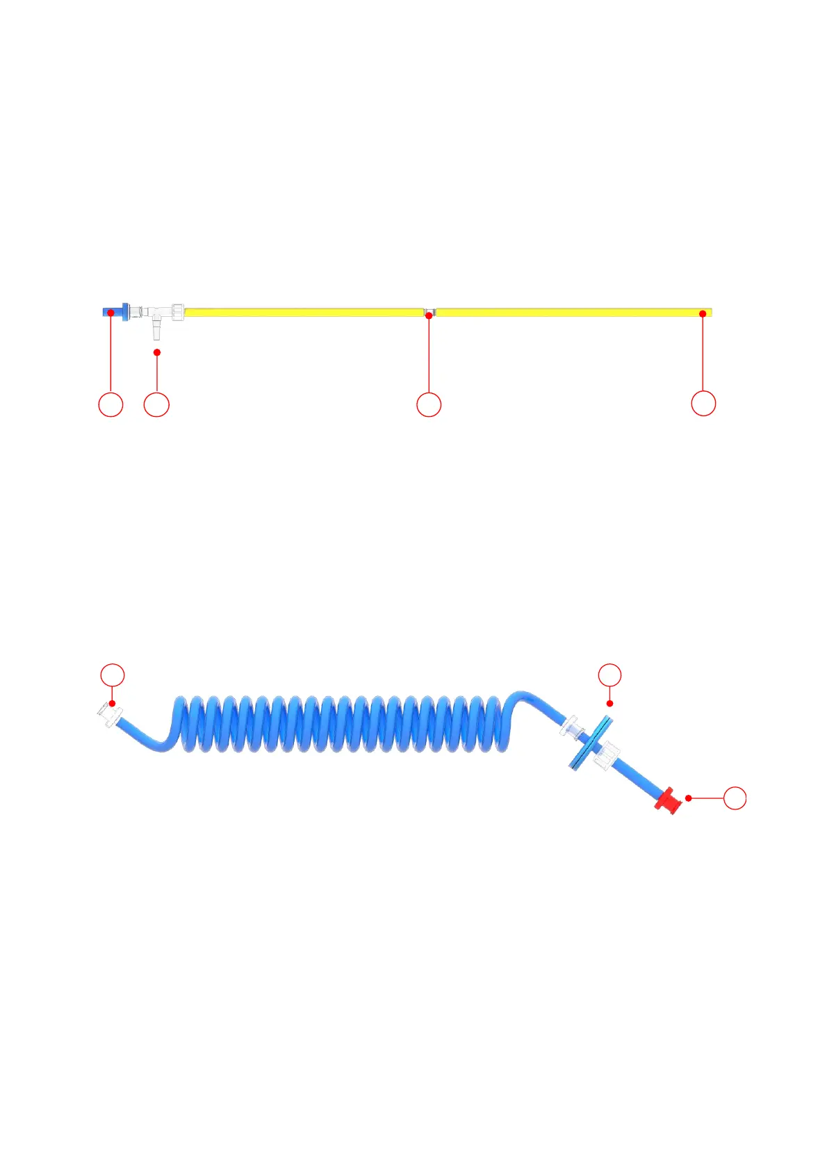
Figure 9. Calibration Kit
5.7 Tube-A
Tube-A (K in Figure 3) is used to connect the Gas Inlet connector of LEO to the Tube-B if the gas to be
sampled is dry or to the Gas Outlet connector of the Moisture Trap, if the gas is humid.
Figure 10 shows Tube-A. Connect the red connector (1 in Figure 10) to the green end of Tube-B (1 in
Figure 11) when sampling a dry gas or to the Gas Outlet connector (labeled green) of the Moisture Trap (1 Figure
7) when sampling a humid gas. The clear connector of Tube-A (3 in Figure 10) must be connected to one of the
Gas Inlet connector of LEO (see Figure 46 for the measurement in Diffusion Mode or Figure 48 for the
measurements in Aspiration mode). A hydrophobic filter (2 in Figure 10) is fitted in order to avoid water collection
at the Gas Inlet.
Figure 10. Tube-A.
Note ► Okolab suggests to replace the filter every six months.
Note ►Remove the protection caps from Tube-A before using it.
5.8 Tube-B
Tube-B (J in Figure 3) is used to connect the sampling Gas Port to the Tube-A if the sample gas is dry, or
to the Gas Inlet connector of the Moisture Trap if the sample gas is humid.
Figure 11 shows Tube-B. The green connector (1 in Figure 11) must be connected to the red connector
of TUBE-A (1 in Figure 10) when sampling the dry gas or to the Gas Inlet (labeled green) connector of the Moisture