iTrans Fixed Point Single/Dual Gas Monitor System Wiring
(P/N: 77023554-1) iTrans User Manual 4-3
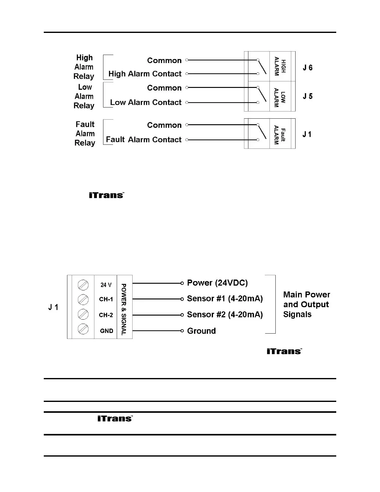
Figure 4-1. Alarm Relay Connectors J6, J5 and J1
4.4. Power and Output Wiring (J1)
Connect the power and signal wires to the appropriate wiring terminals
as follows.
24 V: Connect 24 VDC (12-28 VDC) supply power
CH 1: Channel 1, 4-20 mA output signal
CH 2: Channel 2, 4-20 mA output signal
GND: DC return
Figure 4-2. Power and Signal Connector J1 on the
NOTE: Use supplied green conductor for enclosure ground. Public 485 GND is
to be used for ModBus digital ground.
NOTE: The is a 3- or 4-wire 4-20 mA device. For dual sensor
configuration you must have a second 4-20 mA signal wire pulled to the unit.