System Wiring iTrans Fixed Point Single/Dual Gas Monitor
4-4 iTrans User Manual (P/N: 77023554-1)
NOTE: When not using 4-20 mA outputs, use the supplied resistors to connect
CH-1 and CH-2 to GND. If these resistors are not connected and the 4-20 mA
outputs are not used, a “P” will appear on the display, indicating an open loop
condition.
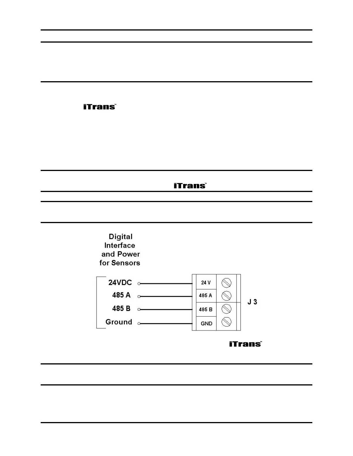
4.5. Sensor Wiring (J3)
Connect the sensor wires (for on-board, remote or stand-alone) to the
appropriate wiring terminals as follows.
24 V: Red wire from sensor head (Red wire on BBIR)
485A: Yellow wire from sensor head (White wire on BBIR)
485B: Black wire from sensor head (Green wire on BBIR)
GND: Green wire from sensor head (Black wire on BBIR)
NOTE: Shielding from either the controller or remote sensors should be bonded
to the enclosure screw located inside the .
NOTE: The 24 V terminal supplies 24 VDC to the sensor for power. This
terminal should not be connected to the output of a 24 VDC power supply.
Figure 4-3. Sensor Connector J3 on the
NOTE: For dual-sensor configurations, place both of the same colored wires in
the appropriate terminal block and firmly tighten.